| This first photo shows use of a height gauge to check the required height on the buffer beam. My standard is to set the coupler centreline 12mm above rail. This corresponds to the NMRA standard for 4mm scale. This is a little below scale height for UK practice as applied to Mark 1 coaches etc. but allows the somewhat overscale Kadee knuckles to fit comfortably under the gangway centre buffers. | |
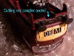
| On this model the space between buffer beam and bogie frame is limited and the coupler pocket for a KD No.5 will not fit, I therefore chose to use a 30 series coupler pocket with a centre shank coupler and the spring mounted below the shank to minimise the recess needed in the buffer beam. After cutting out a recess as shown here | |
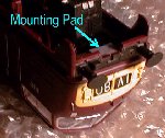
| a mounting pad is cemented behind the buffer beam, A total thickness of 1.5mm was required which I cut from 60thou sheet. | |
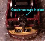
| The coupler pocket was then used to mark out and drill a fixing hole for the Kadee screw. This needs careful drilling as it passes through both the plasic skirt section and the metal chassis block and coincides with a thick section on the chassis. After drilling the hole is tapped using the Kadee tap, the tapping is done from the top so the tap does the hard work through the chassis beforecutting into the plastic section. The coupler can now be fitted , | |
the height checked and a trial
run with a train carried out.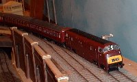 |
 |
| If all is in order cosmetic work on the buffer beam can now be completed. | |
| sections of the front skirt will need to be cutaway to fit round the coupler pocket. | 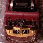 |
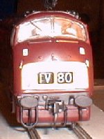
| See comparison here. |

