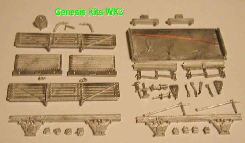
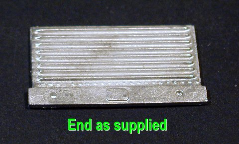
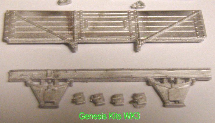
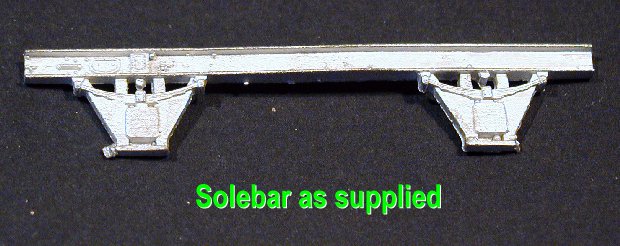
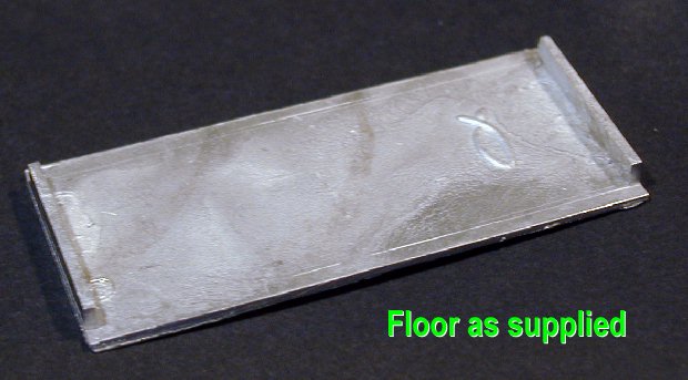
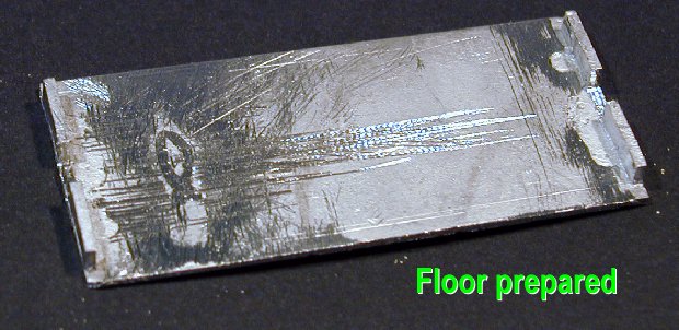
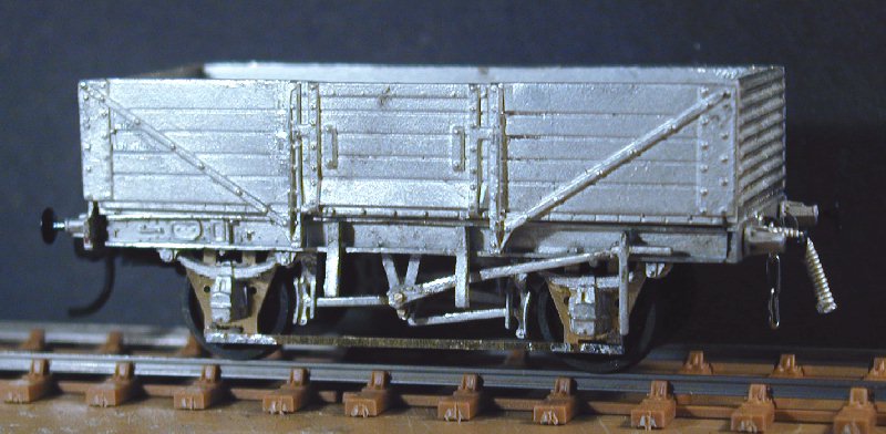
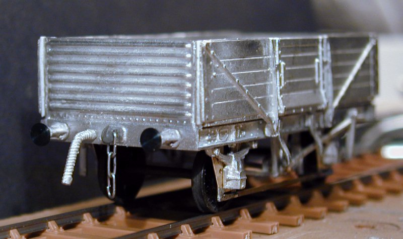
| The Kit, parts: These kits are cast in Pewter and come packed in a plastic bag. All parts arrived in good shape needing only some cleaning up. Total weight of parts is 74g so the wagon should ride nicely with a sprung suspension. The following parts are included, 1. Floor, the instructions advise that the floor edges shoulds be filed to make the width 30mm. this had already been done as delivered and the floor is square. A Genesis symbol is cast on the underside and will have to be filed off if fitting etched W-irons. There is a representation of planking on the topside of the floor. Sides, two identical sides are provided, they are well finished and the detail is clean, the sloping bottom plank of the door being nicely done, they are commendably thin for castings and have a lip to locate to the floor. There is no detail on the inside. The corner plates are correct only for wagons with planked ends, they are not correct for D1/039 or others with corrugated ends which should have tapered corner plates. 2, 9. Ends, One plain end and one end door are provided, of similar quality to the sides, the ends include the buffer beams which need to be drilled for buffers and for the coupling slot. The supports for the sheet rail, the chalk board and the lamp iron are not provided. There should be a rivetted strip along the top of the end, this is missing. 10. Solebars, The solebars have the W-irons and springs cast integrally with them. The solebar has detail cast in on the left half but not on the right half where it will be masked by the brake levers. The detail is identical to that on the mineral wagon kit. The W-irons are cast in the wrong position, vertically beneath the solebar rather than behind it, because of this the springs have minimal relief, pads are provided to locate the axlebox fronts which are seperate items. The W -irons should be the open type on this wagon so the ones provided are wrong anyway. 2, 3. Axlebox fronts, Two types are provided with 4 of each, the original split cast type and the flat front BR type often used for replacements,the split type need quite a bit of cleaning up, however they suffer from the same problem as the springs, they have insufficient depth and will not be useable with etched W-irons unless a spacer piece is made up. 2, 3. Brake gear, Two hanger and shoe assemblies, two Vee hangers, two brake levers. This is provided for a Morton brake which is correct for some of this diagram, the hanger and shoe assemblies are correctly handed. 4. Vacuum gear, One cylinder and two low type vac pipes are provided, A wire will be needed to represent the brake cross shaft which is not provided. Buffers, Four cast spindle buffers provided are OK if you don't want sprung buffers, need a little cleaning up. 3. Couplings, Two dummy hooks provided but would not be much use even for a showcase model as they have no provision to hang a chain. Also provided are brackets to hold Hornby couplers, those won't be wanted either. Door springs, Four of these are included and four are required . 3. Wire, Two bits of wire are provided, the instructions suggest using it for W-iron tie bars if you fit the vacuum gear, these tie bars should be flat bar. |
Click on the picture for an enlargement.
|
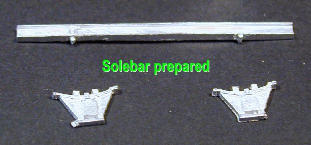
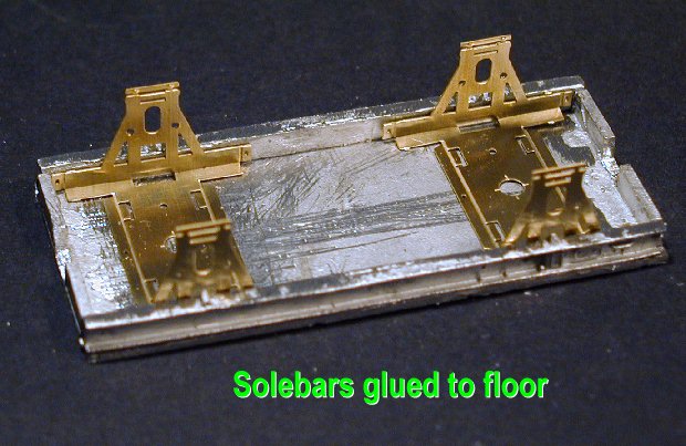
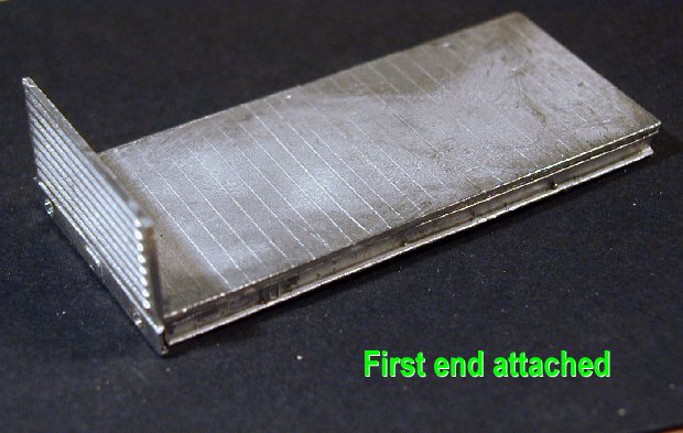
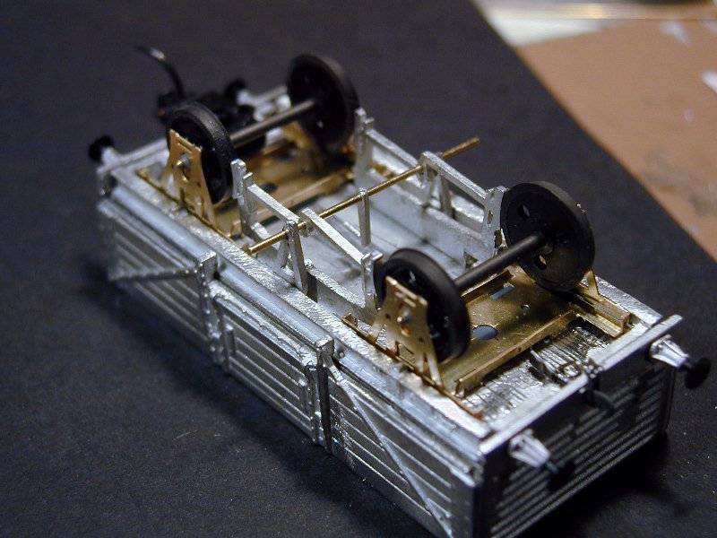
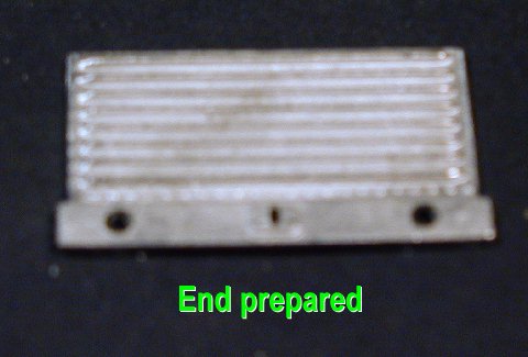
| The Kit, assembly. Preparation For P4 the list of additional parts gets a bit longer as usual, Wheels and bearings, sprung W-irons, tie bars for them, springs and axleboxes, etched Vee hangers, couplings and sprung buffers, and fittings for the sheet rail should do it. First step, find these bits, then work on the running gear. I will use Bill Bedford sprung W-irons so first up is to fold up a pair to use for fixing the solebars to the floor. Then to clean up the solebars, removing the W-irons and springs but leaving the spring shoes and bump stops. 7, 8. The floor was already at the specified 30mm wide so only needed treating at the ends as specified in the instructions. I cut out the centre of each end to allow for 3-link couplings and trimmed the width of the ends to 25mm to give a close fit on the Bill Bedford W-irons. 5, 6. Body The solebars were then attached to the floor. The kit instructions advise, either soldering or superglue. I used superglue for this wagon. 12. Trial assembly of the sides and ends shows up a couple of issues that need to be resolved. The ends are too narrow, the floor cannot be narrowed to match or the solebars will not fit, and the floor width is correct anyway. So the joints between sides and ends need packing, I used 20thou microstrip for this. Secondly the ends come out high, the ledge provided to locate on the floor is not at the right level and has to be filed off. The ends should be drilled for buffers and have the coupling slot opened up at this stage. 11. This done the body can be assembled, and then the pilot holes for buffers drilled right through. 13, 14. W-irons These are made up to the Bill Bedford instructions complete with wheels and then tried in place to check the height. A 30thou plasticard packing was required for each W-iron.
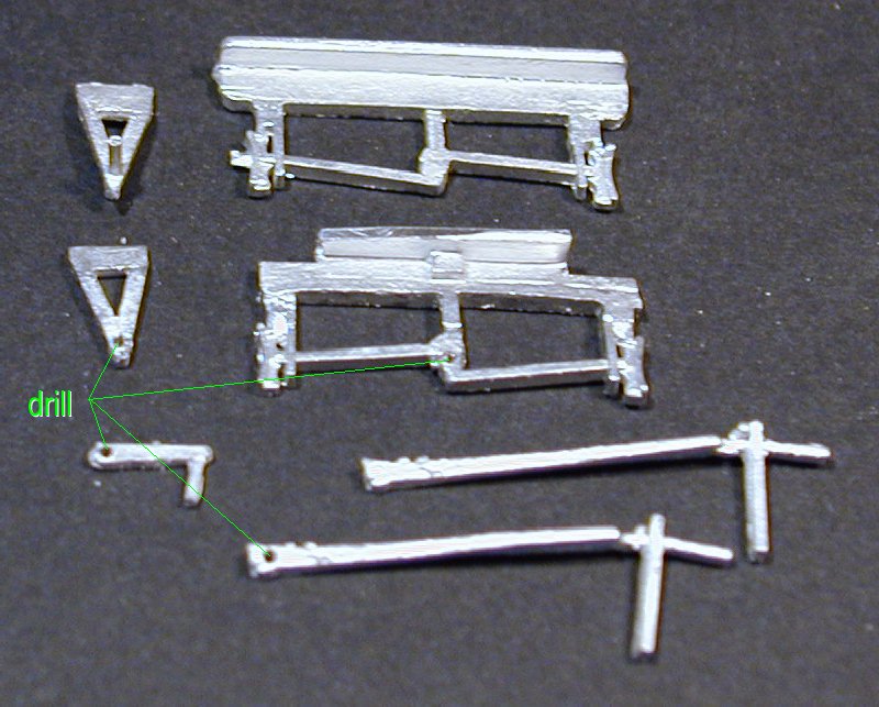
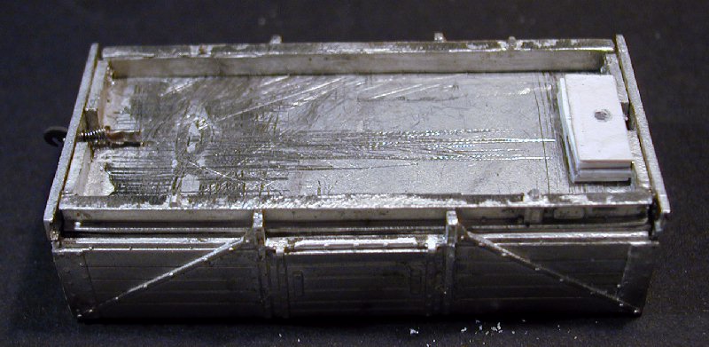
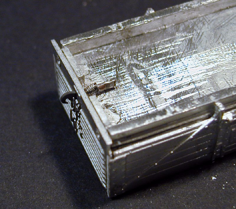
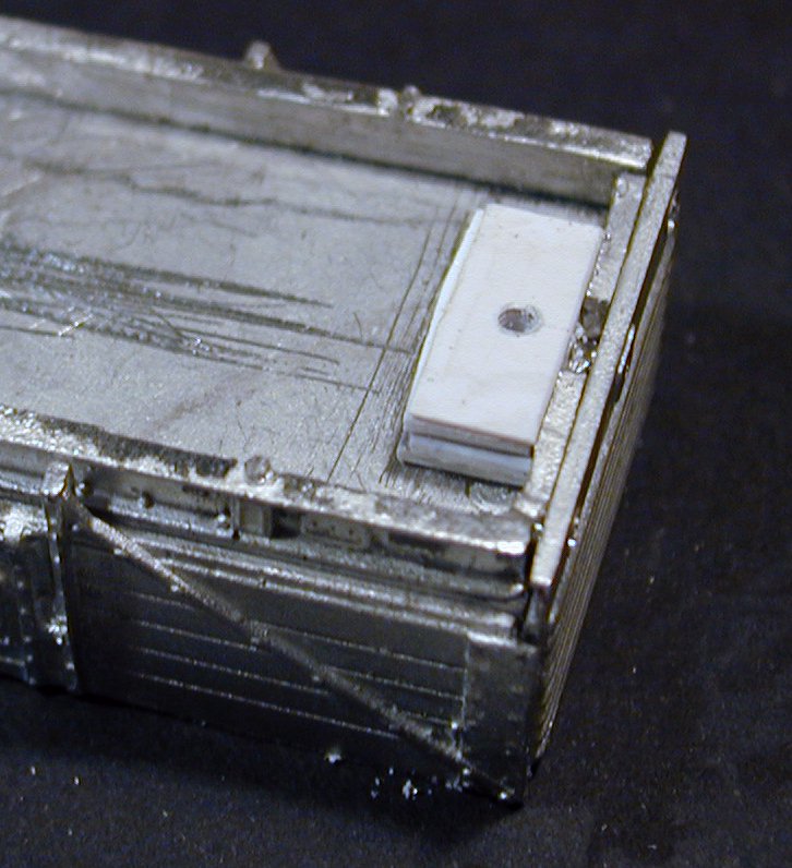
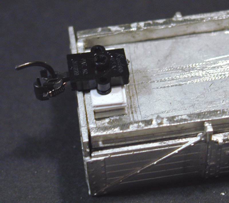
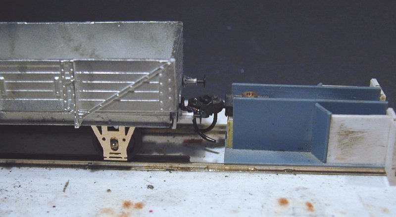
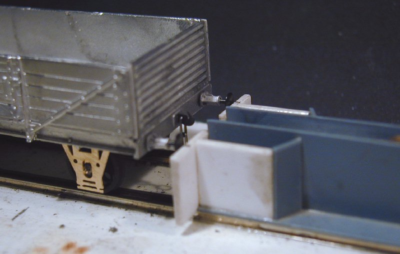
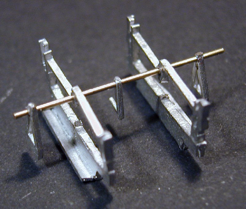
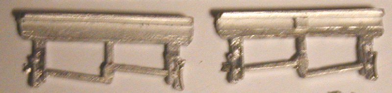
Brake Gear The various items of brake gear needed to be drilled for the cross shaft and trimmed here and there to fit between the W-irons. This picture shows modified and unmodified components. 15. Note that neither of the brake levers supplied have any representation of the Morton clutch. The instructions suggest fitting one above the cross shaft. Therefore this one should not be drilled. Couplings To try both versions I decided to fit 3-link couplings at one end and Kadee at the other. 16. For the 3-link a slot was carefully opened in the headstock and a Studiolith coupling fitted with a Slaters spring secured with a crimped on hollow rivet. 17. For the Kadee a plasticard mounting block was superglued to the underside of the floor and then drilled and tapped to screw fit the Kadee 42. 18, 19. Buffers I find sprung buffers neccessary for good performance on my layout so the kit buffers were replaced by a sprung set from MJT assembled to the MJT instructions and superglued in place after drilling out the headstocks to suit. 21.The wagon was then set temporarily on its W-irons to check the height of buffers and Kadee, 20, 21, all was well. The W irons were then superglued in place.
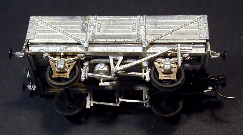
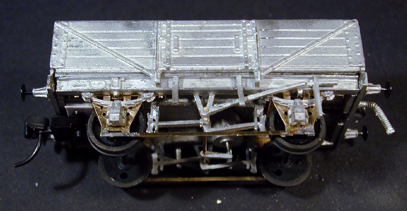
Brake Gear and Axlebox Assembly After drilling all the components as above and checking that the brake shoes will line up with the wheels the brake shoe assemblies, Vee hangers and vacuum lever were assembled on a length of 0.9mm brass rod.22. (Note that the Vee hanger on the Morton clutch side needs a second hole for the clutch pivot). This assembly is then set on the floor of the upturned wagon, lined up correctly and superglued in place.23. Next the brake cylinder is fitted and superglued to the floor and the operating lever. The brake hand levers are now fitted, directly to the cross shaft on one side and on a short piece of brass wire to the higher hole in the Vee hanger on the clutch side. Excess wire can now be cut off with flush cutters completing the brake gear. 24, 25. The axlebox spring units are MJT 2241 RCH Oil. These have a locating lug on the spring hangers meant to fit behind the solebar, these lugs need to be removed and the axlebox holes opened out with a burr in a minidrill to provide room for the bearings to move with the springs, the axlebox/spring units are then superglued in place. 24, 25. The door springs can now be bent to an appropriate shape and glued to the solebar, best to look at photos, they need shortening a bit. 28. Brass strip tie bars are soldered across the bottom of the W-irons and the vacuum pipes fitted into a hole drilled in the headstock, not correct but no other practical way of fixing it unless you make up a complete new pipe arrangement. The wagon is now complete and ready for painting. 28, 29. Finished weight came to 68 grammes, gives good operation on the springs. Keith Norgrove, January 2003.
Genesis Follow Up From: "Ken Bridger" Thanks for the honest review of the kit. Some of the justified comments you have made have already been rectified since I sent you the kits.
The kit was originally designed to be fitted which didn't have a sheet bar and had closed W-irons. But I found that on the fitted version it had J hangers and I presumed that this was the only difference. Open W-irons are on the way, also J hanger type. I have Don Rowlands book now. W-irons cast beneath the solebar. I understand what you mean. If I was to cast them on the rear they would be too close to the wheels especially on P4. It would mean 1mm thick casting plus moving the wheels out to 18.83mm. Get me! Let me know your thoughts on this. W-iron tie bar. I have had problems with this one. Scale thickness tells me they should be about 0.5mm. Brass strip bends easily at this thickness so I am trying wire. When painted it looks the part. Yes, no! Have I dug myself out of the hole yet. I do value your honest view, so please let me know if there is another kit you would like to review. How about the armour plate bogie wagon, ready soon. The first few kit were a demonstration to show the limitation of this type of pewter, a bet with some of the lads. But it turned out to be a better material than white metal in certain areas. So what started as a simple one off trial has now gained my interest in wagons. I'm just a novice at the moment but i'm getting there. Ken |
|


