| MODEL RAILWAYS | APRIL 1972 |
|
|
| MODEL RAILWAYS | APRIL 1972 |
|
|
LOCOMOTIVE DRIVING
BOGIE & TENDER WHEELS
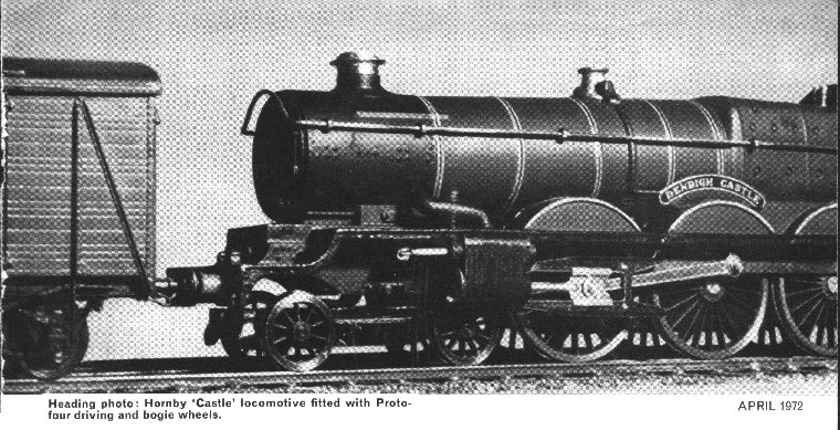
DEVELOPMENTS IN PROTOFOUR
A report by the Model Railway Study Group
J. S. BROOKSMITH, M. S. CROSS, Dr. B. E. WELLER
In the article published last month, the development of
carriage and wagon wheels was described, and while there may have been difficulties in the
process, they are as nothing compared to the problems associated with locomotive wheels.
The steam era on British railways saw several hundred distinct types of steam locomotive
in regular service. Any one of these might kindle sufficient enthusiasm in the modeller to
be included in his building programme, but unfortunately most of these potential models
will never be built.
The reason for this is the lack of suitable wheels. Wheels are essential to locomotive
construction and operation; indeed, they are probably the most important single item in
locomotive building. This is because they are distinctive in appearance, they must run
true, their measurements have to fall within fine tolerances, they must be compatible with
the track standards chosen for the layout, and they must appear authentic.
To incorporate all these factors into a successful model wheel is
beyond the capacity of most modellers, who normally do not have the specialised knowledge,
the detailed drawings, the range of expensive tools, the patience, and above all, the time
to carry out the work. Their choice of locomotive is in practice limited to those types
for which commercial wheels or chassis are adaptable, and, as with few exceptions
commercial wheels are quite different in form to the prototype wheel, the hobby suffers an
incalculable loss of interesting models and their would-be modellers.
No doubt as a result of their complex design, true-to-scale 4mm/1ft locomotive wheels
previously have never been developed for commercial production, with the exception of the
Beeson range. To assess the problems and to find satisfactory solutions, it is necessary
to examine the prototype wheels and to discover the factors which make them what they are.
The typical locomotive wheel is in many respects a reproduction in metal of the road coach
wheel of two centuries ago. The design stabilised in the form of a cast steel centre
containing boss, spokes and rim, to which a steel tyre was fitted by shrinkage. The tyre
was usually secured by a Gibson ring, which fitted into a groove at the rear of the tyre
and prevented parts of the tyre leaving the wheel in the event of breakage. The tyre was
both thicker and wider than the carriage and wagon tyre, being 3 - 4 in. thick and 5 - 5ľ
in. wide. The wheels were fitted to steel axles by means of very heavy pressure and so
formed an immensely strong and stable unit, as witness their ability to survive highly
destructive accidents with relatively little damage.
Early locomotive wheels contained spokes of rectangular section, but later wheels tended
to have spokes of oval section, probably because the latter offered less weight for a
given strength. Regardless of section, spokes usually taper in both width and thickness
from the wheel centre to the rim, and usually have a pronounced flare where they join the
boss. The taper is generally incorporated into the front face of the wheel, so that the
boss stands well proud of the tyre face. There are certain wheels in which the taper is
applied to the rear face, however, so that the boss lies virtually flush with the tyre
face. Some L.N.E.R. and B.R. wheels are of this pattern, presumably to give more clearance
for large outside cylinders.
Exceptions to the spoked wheel were rare, the most notable being the L.N.W.R.'s H pattern
and the Bulleid Firth-Brown wheels of the S.R. 'Pacifics'.
The crank boss was cast integrally with the centre and its accompanying pin could be
located either in line with a spoke or between a pair of spokes. On outside cylindered
engines the throw of the crank was of course equal to the stroke of the pistons. This was
generally 24 - 26 in. but could be as great as 30in. on the G.W.R. express locomotives and
as little as 12in. on diminutive dock tanks. Where inside cylinders were used the crank
pin throw and the piston stroke did not necessarily coincide. The crank boss could be oval
or pear-shaped according to the whim of the designer and the L.N.W.R., ever
individualistic, used large circular crank bosses at one period.
There was considerable variation in the number of spokes used for a given wheel diameter.
It could even happen that two locomotives of the same type, one built by the railway
company, the other by outside contractors, had different spoke numbers. The number of
spokes could fall between the 24 of the G.N.R. 'Singles' and the 9 of the Peckett tanks;
even numbers were much preferred to odd, though the latter were by no means rare. Despite
variations, a logical pattern appears when the main types of wheel are compared on a chart. Bogie and tender wheels in particular fall into three main sizes.
Although a certain standardisation of wheel diameters and spoke numbers is possible, there
remain wheels of individual character inevitably, such as the 19-spoked 7 ft 3 in. L.Y.R.
and the 22-spoked 5 ft 8 in. N.E.R. drivers.
The form and position of balance weights is the most diverse feature in a notoriously
variable context. The weights in driven wheels were provided to balance the cranks and
coupling rods. On outside cylindered locomotives, the wheels carrying additional
connecting rods were fitted with correspondingly larger weights. Usually these were placed
at a point on the rim directly opposite the crank and pin, but on locomotives with three
or more cylinders and or 120 degree cranks the balance weights might appear at seemingly
random positions about the rim. Weights were often cast integrally with the wheel centre
in the form of graceful crescents, but not all designers were so artistically inclined and
a pair of plates filled with packing and bolted to the spokes might suffice for others.
One of the holes in patterned wheels might be filled with metal to provide balancing
weight.
|
||
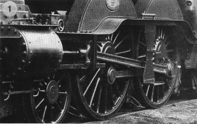
| 1. Driving and bogie wheels of G.N.R. Large Atlantic No. 301. Note the flare of the spokes, the close spacing of the drivers, the flush-ended crank pins, and the size of the connecting rod big ends far wider than in the average model. | 2. Bulleid Firth-Brown wheels on Southern Pacific No. 34057. | 3. The rear-face tapered wheels of L.N.E.R. Pacific No. 60156. |
Crank pins were of several sizes and diameters, and could have
circular or hexagonal locknuts, and in situations where restricted clearance was the rule,
for example behind the connecting rod, the end cap could be fitted with a recessed
locknut.
With components of such complexity, it is hardly surprising that model locomotive wheels
rarely appear in their correct form. Quite apart from the difficulty of incorporating
prototype features, there are other, more serious limitations which inhibit the
manufacturer and modeller. These limitations stem from the use of compromise standards for
track and wheels.
As was pointed out in the last article in this series, the minimum width of a model wheel
must be at least twice the maximum value of the crossing flangeway. This means that in
B.R.M.S.B. modelling with 1.25 mm flangeways, the wheel must be at least 2.5 mm wide, or a
scale 7˝ in. In H0 modelling the situation is even worse as 1.35 mm flangeways demand
wheels at least a scale 9in. wide. A well-known commercial wheel used in many kit models
is 3.6mm wide, equivalent to 11in., twice the width of the prototype. With wheels of this
kind, splasher and connecting rod clearances prevent the use of any but a reduced gauge
for the track. It follows that while compromise standards continue to be used, there will
be continued frustration for the modeller who wishes to model railways to scale.
B.R.M.S.B. wheels are not only wider than scale, but also deeper in the flange. The
standard B.R.M.S.B. flange is no less than 2 in. deeper than scale equivalent, and G.N.R.
'Atlantics' and G.W.R. 'Star' and 'Castle' class locomotives in which the prototype
flanges of adjacent wheels are no more than an inch apart, will remain unbuilt or
distorted. Even seemingly innocent locomotives may provide splasher clearance problems for
scale diameter wheels, and in EM Gauge, let alone 00 , the tips of wheel flanges have been
known to foul the boiler barrel behind the splashers owing to the reduced track gauge
used.
When problems of this nature drive modellers and manufacturers alike to the use of small
diameter wheels and flangeless centre drivers, it is clear that there is no incentive for
the production of correctly scaled wheels for compromise standard modelling.
In Protofour where scale equivalent values are used throughout, no such problems arise. A
correctly scaled Protofour wheel will fit a correctly scaled superstructure just as in the
prototype. It is practical therefore to produce correctly scaled wheels for particular
prototype locomotives where a similar programme for compromise standards would run into
serious difficulties. It was also necessary for the Model Railway Study Group to develop
such wheels to an entirely new specification.
The required basic characteristics of the new wheels were as
follows:
1. Concentric wheel tread of correct contour.
2. True running of the wheel on the axle.
3. Maintenance of the correct BB gauge.
4. Authentic appearance.
5. Correct crank throw.
6. (For model purposes) Electrical insulation of axles and crank pins from the tyres.
7. No integral balance weights.
8. Fine adjustment of quartering.
|
| Analysis of Locomotive Driving
and Bogie Wheels The chart covers some 350 different types of British locomotives. The driving and bogie wheels are placed on the chart in accordance with their spoke number and nominal diameter. The latter is given in feet and inches, and also in millimetre equivalents for 4 mm scale. A model wheel equivalent to 2« in. less than the nominal diameter of the prototype may be used for a particular model as prototype wheels were reduced by this amount during service. The grid on the chart indicates the axes on which the majority of driving wheels fall |
Many promising lines of development were followed, but most
disclosed some factor that prevented the production of a really successful wheel.
Eventually, design stabilised in a form similar to that of the C. & W. wheel, with
certain special features. A standard range of steel tyre sizes is fitted with centres of a
hard plastic material moulded with full spoke detail and flare. The centres are designed
using dimensions taken from existing prototypes wherever possible and the carrying wheels
are of a standard form which allows them to be used with any of the drivers to give the
impression of a matching set.
Bogie and tender wheels use a standard 2.2 mm diameter axle with either flush ends for
inside bearings or pointed ends at 26mm spacing for outside bearings. The carrying wheels
are a light force fit on the axles and are intended to facilitate assembly by the
modeller, being secured, when finally positioned, through the use of locking compound.
|
||
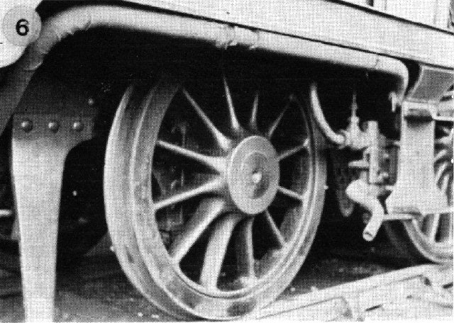
| 4. L.B.S.C.R. 0-6-2T Driving wheel with pear-shaped crank boss and axle end with centre-pop mark. | 5. British Railways standard 9-spoked bogie wheels. | 6. L.B.S.C.R. 0-6-2T trailing wheel. Note the pronounced flare of the spokes into the boss. |
If driving wheels are set on smooth axles, however, they have a
tendency to slip on the axle if mishandled. Secondly, and very importantly, any distortion
of the centre bore during fitting will reveal itself in the form of wobble, magnified at
the rim owing to the relatively large diameter of the wheel. Thirdly, the axle has to
carry considerable traction and braking forces, and to transmit these through the wheel
centre. The fourth problem, and a major one, is quartering.
There have been several attempts to solve these problems in the past, though few have been
completely successful. Perhaps the best known is the splining of the axle end to give a
positive grip to the wheel centre. Although this method gives generally satisfactory
results, it has some disadvantages. Should quartering be inexact when the axle is forced
into the wheel it is virtually impossible to correct the fault, as removal of the wheel is
fraught with danger, either of damage to or of distortion of the wheel, and on reinsertion
the axle will tend to follow the previous grooving rather than a new setting. Furthermore,
the gouging action of the splines may remove more material from one part of the bore than
another, giving eccentric running. A second familiar method of mounting is the squared
axle end and squared wheel centre. This is satisfactory so long as the squares and
crankpin bores are exactly positioned; fine adjustment is virtually impossible.
These problems were avoided in Protofour by the use of a standard 1/8in. axle with tapered
ends. The Protofour driving wheels contain tapered metal inserts which match the taper of
the axle end. This offers many advantages. There is no distortion or gouging of metal
during wheel mounting, simply a progressive tightening of the wheel grip, and an even
pressure at all parts of the wheel bore. The wheel thus retains its true-running
properties despite the firmness of the grip. Furthermore, the axle may be removed from the
wheel by drifting it out with a centre punch, without danger of wheel damage. With one
wheel firmly in place on the axle, the other wheel may be quartered with great accuracy
while held in a semi-fast grip before a final press locks the wheel in place at the
correct settings.
The 1/8 in. axles may be set directly into most commercial chassis units or through the
use of reduction collars already available through the Trade. Commercial models may in
many cases be converted to run on Protofour tracks. The axles also have a small centre
mark on the flush ends, a distinctive feature, and the taper reduces the visible diameter
to the correct value.
Crank pin fitting is an important part of wheel design. What is required is a pin which
has a correct throw, is capable of accommodating one, two or more rods according to the
situation, is rigid enough to stand up to the pounding of the drive, and capable of being
replaced when worn. The Protofour crank pin is in the form of a steel screw which passes
from the rear to the front of the crank boss and to which is fitted a replaceable steel
tubular bearing, flanged to provide distancing of the coupling rod from the boss. This is
retained by a washer, and a circular or hexagonal locknut, naturally to scale dimensions.
The bearing may be replaced without removing the screw from the wheel or the wheel from
the axle. The system also prevents the rotational motion of the rods from being
transmitted to the screw. A far cry from the practice of hammering a peg into the wheel
centre!
The wheels are produced without balance weights so that the correct type may be fitted to
the modeller's choice. The first production wheels were run on a Protofour layout at the
Model Railway Club Exhibition in August 1969, and since then the range has been expanded
to contain eight bogie and tender wheel types, and five drivers. This is, of course, only
a beginning.
The new wheels have given superlative performance, and the M.R.S.G. therefore feels that
its approach is a correct one, which will bring benefits to the scale modeller. We would
like to take this opportunity of thanking the Curator of the Clapham Museum for permission
to publish photographs of locomotives stored there, and also Nick Campling of the L.N.E.R.
Society who kindly provided several photographs for this article.
|
||
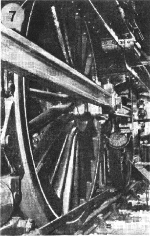
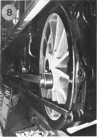
| 7. Midland Compound driving wheel. The coupling rod is mounted outboard of the connecting rod. | 8. L.B.S.C.R. Terrier driving wheel with rectangular section spokes. | 9. G.W.R. 4 ft 7˝ in. pannier tank wheel - the first wheel to be produced in the Protofour programme. |
|
|
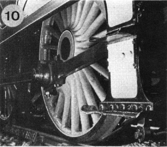
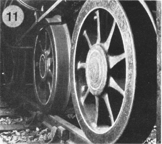
| 10. L.S.W.R. 4-4-0 driving wheel with rounded and flared spokes, ridged rim, and inboard connecting rod. | 11. Metropolitan Railway bogie wheel with rectangular flared and tapered spokes. |
|
|
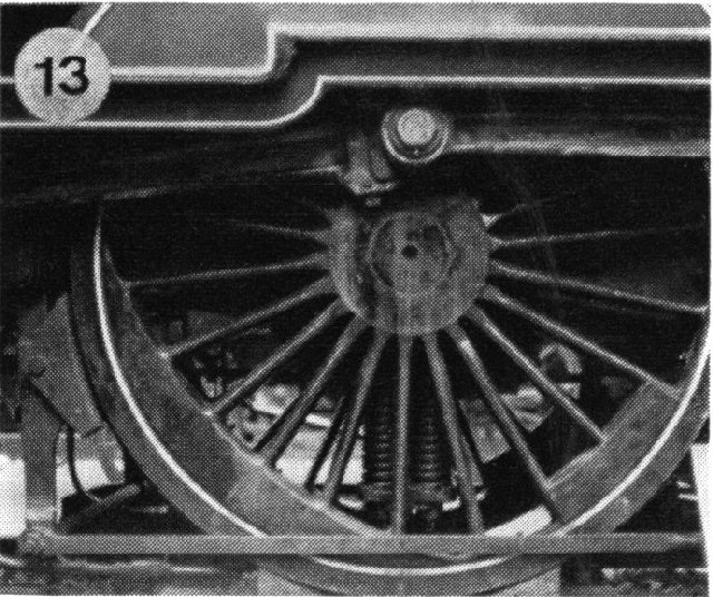
| 12. L.N.E.R. A4 Pacific driving wheel showing the limited clearances between coupling rod and wheel face and the flaring of the spokes into the wheel boss. | 13. The combination of crescent and plate balance weights on the driving wheels of a Midland Compound. |
Photographs 1 - 3 by courtesy of N. Campling. Photographs 7, 8, and 10 - 13 by kind permission of the curator, Museum of British Transport, Clapham.
Copyright - Model Railway Study Group, reproduced with permission.
Back to Magazine Index, Back to Site Index.
K Norgrove 25/04/03