MODEL RAILWAYS

FEBRUARY 1976

DEVELOPMENTS IN PROTOFOUR

LOCOMOTIVE
SUSPENSION

by MS. CROSS
and B. E. WELLER

MODEL RAILWAY STUDY GROUP

photo-1s.jpg (36261 bytes)

In the BR diesel Shunter, the hornblock is placed on the outside of the frame and so the suspension components are clearly visible. Note the overslung multiple-leaf spring, Its attachment to the frame, the direct contact between the central spring strap and the bearing, the square form of bearing with flanges riding over the edges of the hornblock slideways, and the generally massive construction.

Locomotives with rigid suspensions continue to be used by the large majority of modellers. It's interesting to examine the reasons for this preference in view of the fact that such locomotives frequently have poor running characteristics, exhibit unreliable electrical pickup, are frequently noisy and are inherently difficult to construct.

The development of the Protofour system has been extended far beyond the concept of a set of standards to embrace a prototypical track system together with a comprehensive wheel end wagon/coach compensation programme. In these articles the development of the Protofour locomotive mainframe and suspension system is described.

The simpler the mechanism, the less likely it is to go wrong. This axiom has not been lost upon locomotive designers since Novelty failed to beat the rough-and-ready Rocket at Rainhill, and locomotives consequently have tended to be built with almost primitive simplicity and technical innovation has often led to trouble. It should therefore occasion no surprise to discover that the method of suspending both 'Rocket' and 'Evening Star' on their respective wheelsets is Identical - through springs acting upon the axle bearings, the latter riding in vertical slideways in the frames.

It is at first sight surprising that model manufecturers and modellers have persisted throughout the years in producing model locomotives with no compensation or springing whatever. If rigid suspension were adopted in real locomotives both they and the tracks would soon be battered to pieces, but apart from avoiding such obvious disasters the use of sprung suspension provides many other benefits, which may be summarised under the headings Trackholding, Weight Distribution and Traction.

Trackholding ability results from interaction between the wheel and rail contact surfaces, which must be correctly dimensioned and contoured to produce the correct results. However, the wheel and rail must be in firm and continuous contact to produce these results, and springing is the obvious way to ensure this desirable state of affairs,

Weight distribution, while of minor importance to modellers, is of the utmost importance to the locomotive designer. Tracks, bridges and other permanent way installa tions are limited in the loads that they can accept and consequently the designer is constrained by the limits set by the Civil Engineer. Both the Highland 'River' class locomotives and their designer left that railway when it was discovered that this little detail had been overlooked. The springs tend to distribute the locomotive's weight across the wheelbase and by adjusting spring tensions it is possible to arrange for individual wheelsets to carry a greater or lesser proportion of the total load.  Where tracks are lightly laid or liable to be uneven it is a common practice to connect adjacent spring ends by a compensating beam,  this allows the weight to be evenly distributed over the connected wheelsets regardless of the state of the track.

Traction is the outcome of the coefficient of friction developed between the wheels and the rails. Other factors being equal, traction increases in proportion to axle loading. Damp 'greasy' rail and steam sanding are other factors which do not concern the modeller, and so it is safe to assume that the greatest traction in the model will be achieved with all driving wheels firmly in contact with the rails and the weight of the locomotive concentrated upon them.

photo-2s.jpg (14591 bytes)

photo-3s.jpg (13070 bytes)

A detail photograph of the spring, bearing and hornblock of a 4-6-0 express passenger locomotive. Note the underhung spring, and the width of the hornblock; otherwise, the components are similar to those in the first photograph. The leading driving wheels of the Bluebell Railway's 0-6-2T illustrate the LBSCR method of hanging the spring, and also how prominently this component features in certain views of the locomotive.

photo-4s.jpg (20033 bytes)

The central driving wheels of the same locomotive show the relative sizes of the coupling rods and the knuckles, and also the additional knuckle provided for vertical flexing of rods.

In rigidly-suspended models, the slightest unevenness in the track will cause individual wheels to lift from the rail; although this lifting may not be detected by the eye, it nevertheless means that no more than three wheels, two on one side and one on the other, can be guaranteed to be in firm contact with the rail at any particular moment, and therefore that the full traction potential of the model can never be realised.

The almost universal use of 'two-rail' power feed to locomotive models requires constant electrical contact to be maintained. As the continual intermittent lifting of rigidly-suspended wheelsets causes 'making and breaking' of these contact points, the flow of power is likely to be irregular and the ideal conditions for the accumulation of wheel tread deposits are created.

In view of the above, it is difficult to avoid the conclusion that the optimum model performance and the correct representation of the prototype are simultaneously achieved through the use of spring suspension of the locomotive upon its wheelsets.

Many attempts have been made by manufacturers and modellers to disguise the undesirable effects of rigid suspensions, most of which have provided more problems than they solve. They range from overscale wheels and flanges, which bring distorted track settings with them, through rubber and plastic wheel tyres, to that pathetic track-clinger, magnetic adhesion'. It is therefore all the more curious that while manufacturers and modellers have been busily trying to treat the symptoms of the rigid suspension system and learning to ignore the terrible side-effects few attempts have been made to cure the disease.

With the appearance of Protofour a completely new approach to the matter of locomotive suspension became imperative. When the MRSG designed the Compensated Suspension Unit for Carriage and Wagon conversion, the resulting quality of running made the continued acceptance of previous suspension systems impossible. The MRSG therefore listed the desirable features of a prototypical locomotive suspension, as follows:

1. Compensation of all wheels.
2. Scale appearance.
3. Simplicity of assembly.
4. Adaptability of use.
5. Accessibility of components.
6. Minimal cost.
7. Minimal maintenance.
8. Continuous electrical contact between rail and motor.
9. Quiet running.

The components involved in the design were listed as:

1. Mainframes,
2. Mainframe spacers.
3. Hornblocks.
4. Bearings.
5. Springs.
7. Coupling rods.
8. Bogies and Trucks.
9. Electrical Pickup Gear.
10. Transmission.
11. Motor,

In designing these parts it quickly became apparent why no similar system had appeared - each part is dependent upon all of the others. Every component must be designed twice; firstly to fulfil its function, and secondly to integrate with the others. Once a dimensioning chain is established it is necessary to work back again to ensure that parts are held to scale dimensioning.  However, the operation is resolved with care and concentration, and as most of the listed parts have prototype equivalents, it is logical to commence with an examination of the layout of a steam locomotive, which is, after all, what we are supposed to be representing in our models.

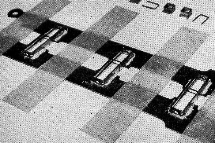
British steam locomotive mainframes are normally cut from 1in -1¼in, steel plate. They incorporate slots to clear the axles and to reduce weight and are predrilled to mount components such as the cylinders, motion brackets and brake hangers, and are contoured to strengthen potentially weak locations. Spacers serve to hold the otherwise flexible frames rigidly at the correct distance apart and the components within the frames in correct alignment.

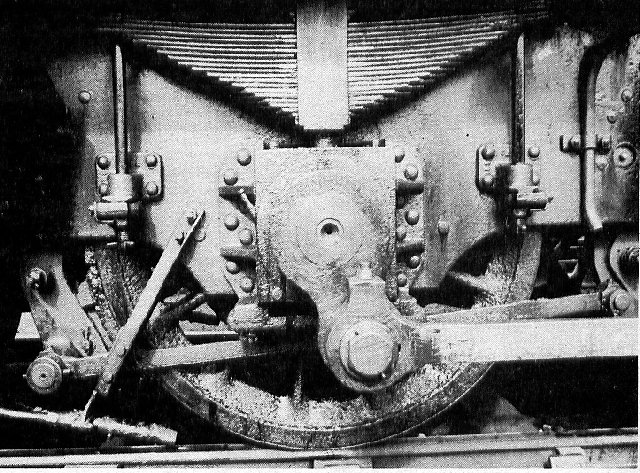
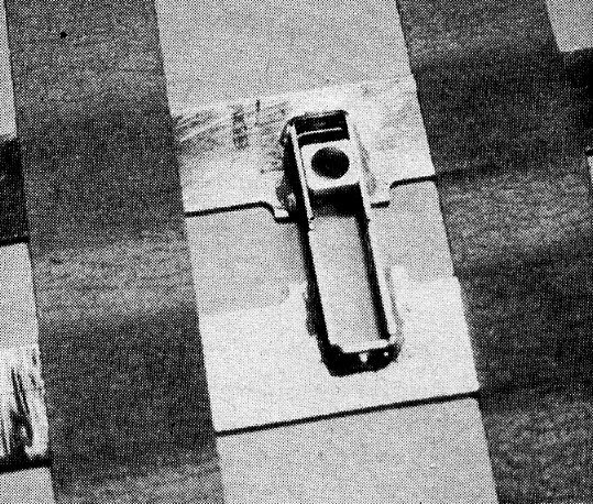
Hornblocks are heavy, cast flanges mounted over the axle slots to form vertical slideways in which the axle bearings may ride. Their heavy construction is necessary to enable them to accept the force of the pistons and other running and braking forces.

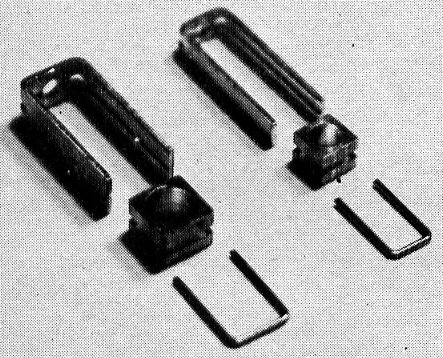
Bearings are fitted over the axle journals and consist of an inverted 'U' containing a semi-circular bearing surface, to which is attached an oil reservoir with wicks to transport the oil to the axle journals. The bearing has a square external form with flanges which fit over the vertical hornblock slideways. The hornblocks thus position the wheelbase both longitudinally and laterally in the frames.

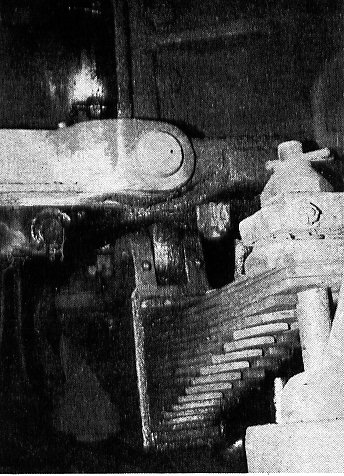
Springs are generally of the multiple leaf type with their ends retained in hangers fixed to the frame and with the centre strap attached directly to the bearing. Some designs featured coil springs in place of the leaf type, and others, particularly those with bar frames as in America and Europe, incorporated compensating beams.

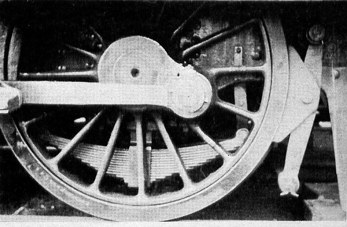
Wheelsets are familiar to modellers as they are easily examined in photographs. How ever,the treatment of the rear faces may vary, some designs having concave taper and a recessed boss, and some, as in the NCC Broad Gauge locomotives, having the wheel reversed so that the front taper brings the tyre to the desired gauge,

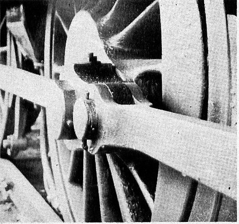
Coupling and connecting rods are precision-machined to the axle spacings. Their end knuckles,which contain the bearing surface for the crankpins, are about twice the height and width of the rod itself. Some designers preferred rods milled to 'I' section but these are not so stiff as the plain rectangular section, as BR's 'Britannias' proved by bending several.

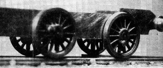
Bogies and Trucks are miniature frames which rotate about a pivot and are permitted, limited, controlled sideplay relative to the frames. They contain miniature hornblocks and springs and retain wheelsets just as in the mainframes, but their lateral movement adjusts the wheelset radially to the track and allows the locomotive's wheelbase to flex at its extremities. A similar effect is obtained through the use of radial' axleboxes in which the hornblocks are machined radially and the wheelset with its bearings traverses an arc.

In translating full-sized practice to model operations, the following features need to be noted:

1. Wheels are permanently fitted to their axles to form wheelsets and are gauged, quartered and fitted with crankpins before are mounted in the frames.
2. The wheelset is fitted with bearings and the latter introduced into the hornblocks, where the wheelset rides vertically under the influence of the springs. A strap across the hornblock ends prevents the wheelset from falling out of the mainframe when the locomotive is lifted.
3. Axle-to-bearing, and bearing-to hornblock surfaces are generous, as they have to be to accept the forces and pressures involved. Sound engineering practice suggests that the length ofthe bearing should not be less than its diameter.
4. There is no vertical movement of the bogie relative to the mainframe, all movement of the wheelsets taking place in the hornblooks. The bogie carries the locomotive weight on pads formed in the upper surface, which allow the bogie to slide laterally relative to the frame. The side control springs act on a bolster attached to the central pivot, so that the bogie moves relative to the bolster. Inadequate lubrication of these sliding surfaces may have been a contributing factor in the high-speed derailment of a LSWR boat train in Salisbury station, back in 1906.
5. Bogie wheelsets are generally sprung by means of a single longitudinal spring on each side of the bogie. This is not easily seen as it is carried in the inverted position between two plates ofa hollow beam. The centre strap is attached to the bogie frame, the ends of the spring are attached to the beam, and the beam in turn curves upwards to enter the tops of the hornblocks to bear on the bear ings. There is thus a combined springing and compensating action.


photo-5s.jpg (17426 bytes)

photo-6s.jpg (23461 bytes)

The standard Protofour hearIngs and hornblocks, and their wire cradle retainers - the basic components of the locomotive spring suspension system.

That the flexing knuckles are necessary Is well Illustrated by this photograph of track subsidence in the Erewash Valley in 1965. Stanier 2-8-0s and Black Fives' were operating over these lines at the time.

6. Trucks are half-bogies, a familiar example being the D-framed trailing truck of certain 'Pacific' locomotives, which is pivoted ahead of the firebox and carries the locomotive weight on pads positioned below the cab. Other types of truck had pads shaped as shallow Vees which the weight of the locomotive tended to centre, while others again were fitted with a triangulated suspension which centred by equalising spring pressure at each side of the truck.
7. Wheelsets are mounted in the hornblocks without any sideplay except that developing with wear, and generally have the back of the wheel tyre in close proximity to the mainframe, Therefore, the wheelbase of mainframe-mounted wheelsets must be rigid. The wheelsets of bogies and trucks are similarly without lateral play relative to the bogie or truck frame, This enables them to sense changes in track curvature instantly and to transmit the resulting side pressure via the control springs, thus easing the locomotive into the curve and reducing the wear on the leading driving wheel flanges.
8. Locomotives in which the fixed wheel base is rather long usually carry, thinner-than-standard flanges on the middle wheelsets, to give extra side clearance when rounding curves. In some designs, such as the LNW 0-8-0s and BR 2-10-0s, one wheelset is flangeless. It is interestinq to recall that on the Midland Railway, Paget s brand-new experimental 2-6-2 locomotive with a l7ft 4in. fixed wheelbase became stuck on Syston curve partly as a result of binding flanges. In contrast, on the same railway, Deeleys 0-6-4Ts were given a limited sideplay to the leading driving wheels, and the coupling rods had spherical bushings in consequence.
9. Mainframes were often made in two sections, the 2in. - 2½ins, narrower section accommodating the sideplay of the bogie.
10. Whenever there were more than two driving wheelsets, the coupling rod contained an extra knuckle joint to allow the rod to accommodate to the irregular rise and fall of the wheelsets.

When model practice is examined in the light of the above, much of it seems positively weird. For years, model locomotive frames have been formed as a pair of flat plates drilled for axles and mounted on spacers. This means that the holes must be drilled with great accuracy and in correct alignment one of the most difficult engineering operations to perform without special equipment; the wheels must be simultaneously mounted on their axles, spaced and quartered while attached to the frames, an operation of great complexity and exquisite inconvenience; the coupling rods must be drilled to match the frame hole spacing exactly, and even then can be rendered useless if the crankpins are not of exact throw; in the circumstances,it is a wonder, not that so many modellers come to grief, but that models survive to run at all.

That they have done so is a monument to the strange human propensity for doing things the hard way and doubtless to the use of generous clearances between the parts. These latter enable hammer-blows from the track to be transmitted directly to bearing surfaces both inadequate and impossible to lubricate effectively, and the inevitable result is rapid wear and noisy running, particularly as the drive gearing is constantly changing mesh. While there has been a tendency recently to adopt slotted frames with keeper plates to retain pre-set wheelsets, it is still desirable to draw a veil over wobbly or eccentric wheels, sparking current collectors and the mayhem that must be committed to dismantle the assembly for maintenance purposes.

In turning to more prototypical model locomotive constructional practice it might be of benefit to consider the implications of certain dimensional tables that have appeared recently. Paget's expensive encounter at Syston (the subsequent dead-engine haulage cracked the pistons, which could not be disconnected easily from the cranks) should serve to remind us that model locomotives of necessity have standard flanges on all wheels and yet are expected to negotiate, faultlessly, curves that make Syston look like a racing straight. For this reason, judicious corrections - incorporated in Protofour and the Proto-scales - are necessary.

In conforming to the design requirements, the MRSG finalised the locomotive suspension system in the following manner:

  • Correctly-contoured mainframes (to individual prototypes) slotted to receive hornblocks.

  • Spacers of two overall widths from bands of metal of various sizes.

  • Hornblocks of an extremely effective but simple design which locate in the frame slots.

  • Bearings of a slide-fit in the hornblocks, retained by simple wire cradles.

  • Wheelsets to standard Protofour design.

  • Electrical pickup gear utilising copper-graphite brushes bearing on the backs of the wheel tyres.

  • Floating gearbox with adjustable gear mesh.

  • Rubber pad or any alternative compensation.

  • Motor up to 15mm overall width.

  • Simple and rapid jig assembly.

A detailed description of the design is beyond the scope of this introductory article, and with the Editor's permission will be undertaken in future issues of MODEL RAILWAYS. However, the key to the design is the solution to the problem of providing a satisfactory form of hornblock and bearing, and it is this achievement that has enabled a completely different approach to model locomotive construction to be undertaken. It is now possible for any careful modeller to assemble the running gear for any chosen locomotive using standard parts, simply, accurately, and in the certainty of achieving high-quality running through the sprung suspension. And as the axiom has it the simpler the mechanism, the less likely it is to go wrong!


SimplicIty of assembly. The hornblocks are automatically alIgned by the main. frame slot. and by the inclusion of asIngle wire cradle for each pair. ThIs experImental maInframe is being assembled by mans-of epoxy resIn adhesive, but soldering of the horns to the frames Is equally effective.
photo-8s.jpg (15306 bytes)


The bearing is retained In the hornblock by the wire cradle on which it slide. vertically while- remaining accurately positioned laterally.
photo-7s.jpg (19787 bytes)

The wheelsets fitted to the hornblocks, with rubber pads between the bearings and the tops of the horns. The wire cradles prevent the wheelsets from falling out of the hornblocks. Note the holes In the hornblocks for an alternative retaining pin; the hornblocks have not yet been trimmed to length, nor has the mainframe been drilled for pickup units and brake hangers.
photo-9s.jpg (11719 bytes)


The unit negotiating a displaced running rail. All wheels remain in contact with the track.
photo-10s.jpg (9328 bytes)

Copyright - Model Railway Study Group, reproduced with permission.

Back to Magazine Index,  Back to Site Index.

K Norgrove 25/04/03