 |
| Model Railway Constructor | April 1968 |
PROTOFOUR --- 10 a new scale modelling standard by a model standards study group J. Brook Smith, M. S. Cross, D. E. Jones |
Templates
BRIEF notes on templates appeared in Part 9 of the Protofour series (September 1967 mrc) together with an illustration of an early design. The template design has since been improved, and better methods of use introduced, and it is now opportune to describe the subject in greater detail.
A barrier to successful and enjoyable railway modelling has long been the construction of track. One suspects that the fascinating business of construction itself cannot be the real cause of this; a more likely cause is lack of knowledge of how to set about the operation. Trackwork has always been rather shrouded in mystery, and in the course of the Protofour series, the MRSG has attempted to clear the fog by an analysis and explanation of the factors determining the successful functioning of track.
Completely reliable track may be produced by adherence to five basic rules and the use of sound constructional techniques. In the Protofour system adherence to the five basic rules is ensured by the four gauges (TG. CG. CF. BB) and the contours of the wheels and rail. However, the critical units of any track layout are the switches and crossings. and these must be constructed accurately if they are to function correctly. To achieve the necessary standard of accuracy the modeller must draw out patterns for the units, in which the rails are of the correct length, the leads, angles and timbering are appropriate to the unit, and in which the track gauge, check gauge and crossing flangeway are correctly represented. This draughting operation takes time, and demands patience, some skill and a source of correct information.
The modeller is thus at a double disadvantage. The most critical units of his track must be made under the most unfavourable conditions. If in the circumstances, the modeller's enthusiasm has not already waned, it will certainly do so when it is realised that each turnout on the layout may well require its own individual pattern.
It is therefore clear that what the modeller really needs is a series of patterns for his track units, which should have the following characteristics:
1. Correct scale reproduction of plain track, switches, or crossings. to the standards appropriate to the layout.
2. Designs covering the requirements of the entire layout.
3. Pattern form allowing direct construction on the face of the jig.
4. Pattern size convenient for track planning.
Protofour templates have been designed to carry out precisely these functions.
As explained in previous articles, the correct alignment of the running rails in vertical and horizontal axes is extremely important. Thus it is of importance that the alignment of rails should be maintained during construction, and for this purpose, jig building is the only really satisfactory constructional technique. Protofour templates have therefore been designed to carry out the function of jigs when fixed to a suitable firm, smooth and flat surface. The templates are printed on a special paper noted for its dimensional stability; in this respect they are far preferable to photocopies, which are prone to distortion, and are not really suitable as templates.
The paper templates have four main advantages:
1. They are inexpensive.
2. All templates are identical in scale, and therefore interchangeable.
3. The paper templates are easily fixed to a jig surface.
4. Reduced size printings may be used for track planning purposes.
|
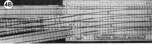
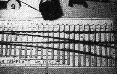
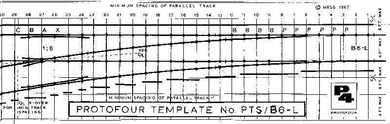
Notes on the Template. 1 Rails are marked as solid lines the width of the rail. 2 Adjacent rails not part of the unit are shown as hollow lines. 3 Adjacent tracks are shown at minimum spacing. Centrelines between tracks are marked as a thin line. 4 Crossover centrelines. showing the minimum back-to-backspacing of plain turnouts combined into crossover roads, are shown as dotted lines. 5 Crossing timber positions are shown as the centreline of the timber. 6 Rivet positions are shown as dots at the intersection of timber centrelines and rails. These also indicate chair positions. 7 Special chairs, eg, block, slide, and crossing chairs, are marked with a reference letter. 8 Timbers are given a serial number to assist in identification during assembly. 9 Timber edging is indicated by a solid line, the outer edge of which represents the preGrouping length, the inner edge the post Grouping length. 10 The serial number of the drawing indicates the switch type and crossing angle. eg. type >B' switches. 1:6 crossing angle, right hand divergence. |
Protofour techniques for track construction can therefore be seen to centre on the principle of the "instant jig". However, before construction commences, it is necessary to know the form of the layout.
Most modellers' layouts differ considerably from the original plan. and were they to be rebuilt, they would probably take yet another form. The reason for this is usually "back-of-envelope" planning. Layouts grow from inconsequential sketches, a station here, a locomotive shed there; the sketches are translated into reality by squeezing the track plan into what is always restricted space. This haphazard process often results in the misjudgment of headshunt lengths. radii and siding capacity, and leads directly to unsatisfactory running in the finished layout. Unfortunately, these incipient defects do not show themselves until the layout is in operation. and then it is too late to tear up the result of hours of work, and to throw away the capital invested in track and materials.
Such expensive, irritating and largely irreparable mistakes can be avoided by producing an exactly scaled plan of the track. To enable this to be made quickly, as well as accurately, track planning templates have been produced as quarter-size reductions (1mm/ft) of the construction templates, printed on a light-tack self-adhesive paper. This allows them to be arranged on desk-top reductions of the baseboard area, and to be positioned. removed and repositioned as desired. This is not only most convenient: it prevents damage to the construction templates during the planning stage.
When using the planning templates, tight corners, minimal lengths. and disproportionate track spacings become apparent at once, and layouts that do not make the best use of space, or hamper the movement of trains, may be changed to more efficient ones before they involve the use of expensive track material. The templates also ensure that turnouts always retain their correct proportions, and thus will accept all stocks. This removes one of the most persistent of planning problems.
The result of Protofour track planning is therefore a saving in expense, owing to the avoidance of mistakes; better running through the maintenance of correct track alignments; greater operational possibilities owing to the accuracy and adaptability of the planning system; and a more convincing, authentic and satisfying layout. Protofour planning templates also enable the maximum possible use to be made of what is normally limited modelling time.
One of the fascinations of prototype trackwork is the manner in which junctions are laid on the curve. This is possible because the junctions are made up from switches and crossings taken from a standard range of types and angles, and combined as necessary for the site in question.
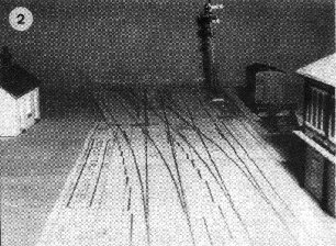
As all the normally found switches and crossings are included in the Protofour range. special model junctions may be built up from individual switches and crossings cut from the templates and reassembled as necessary. Curved turnouts, where not already included in the series. may be made by curving a standard straight formation (see photo, No. 3). As the switches and crossings in these assemblages remain intact, the resulting layout will remain within limits for the stock, and only the radius of the inner curved roads will be critical. The use of these techniques gives a remarkable scope to track planning, which the scale modeller is able to exploit without the penalties of miscalculation, and at minimum cost.
Protofour templates also enable the modeller who has insufficient time or space for a model railway to plan his future layout, the assembled templates give an excellent impression of the final appearance of the layout (photo No. 3) and a veritable Clapham Junction may be built up in an hour or so, using only a board and an armchair. Once a suitable track plan is found, construction of individual units on template jigs may go ahead in the knowledge that the track will fit exactly into place once the baseboard becomes available.
The introduction of Protofour templates is an important development in the technique of model railway construction. It is now possible for a newcomer to construct authentic and completely reliable trackwork without the need for preliminary research and experiment. In fact, at the first attempt he can produce scale model railway track of a standard and authenticity that formerly eluded all but a few experts. Moreover, such track will be closer to scale than any ready-made commercial equivalent.
While these advances are an achievement in themselves, perhaps the greatest improvement in technique is that Protofour templates remove the need for draughting and measurement altogether. Given a template on which the track spacings, the centrelines, the timbering, the rail lengths and gaugings are all clearly marked, and the Protofour gauges to ensure the settings during assembly, ruler measurements become unnecessary, this is indeed a case of "cutting the theory and getting on with the running"!
Protofour templates bid fair to open up a new field of modelling, Many modellers, faced with the unquestioned difficulty of organising the building of a scale model railway from scratch, never get beyond the pure theory of a daydream layout. Others find the study of scale modelling from an armchair a substitute for the building of the layout itself. Well and good; the hobby is there to be enjoyed. The Protofour templates give to all kinds of modellers the opportunity of breaking away from the illusions of single-line track diagrams and substituting working diagrams from which working layouts may be constructed. For the theorist, a new dimension enters into his studies; for the practical modeller, the combination of Protofour templates and techniques brings authentic appearance, steady-riding vehicles, smooth negotiation of junctions, and other hallmarks of prototype operation within his reach.
The next article in this series will describe track construction using Protofour templates as jigs.
|
|
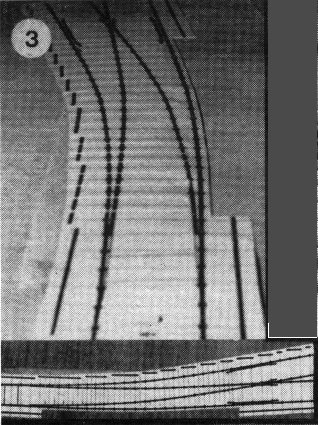 3. Curving a straight turnout template by cutting between the sleepers. Note that the switch and crossing remain unchanged. |
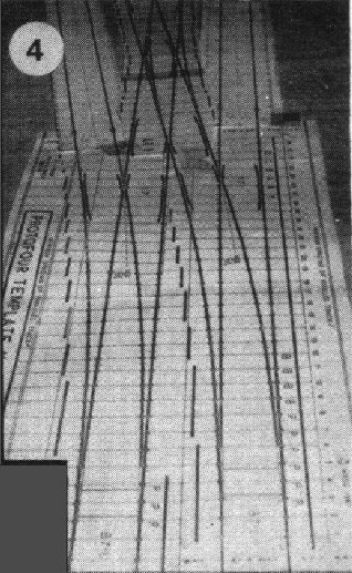 |
4.
The double junction in Photo. 2 seen from another viewpoint. Note the advancement of the
inner turnout. The crossings in the turnouts may be replaced by centreline timbered ones
as in the slips. |
|
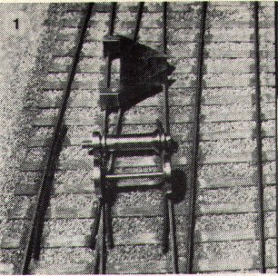
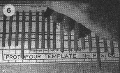
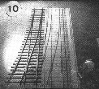
Stages in the construction of a turnout
using a Protofour template as a jig.
5. Template secured to jig surface,
and materials ready.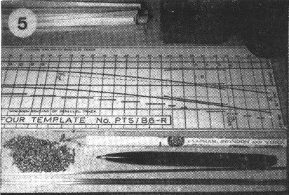
6. Marking the timbers. |
|
 |
7. Timbers with rivets set awaiting the soldering of the rail. |
|
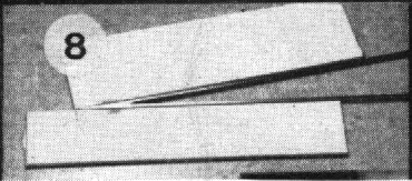
8. Constructing the crossing vee in a separate jig.
10. The completed turnout. |
|
 |
Copyright - Model Railway Study Group, reproduced with permission.
Back to Magazine Index, Back to Site Index.
K Norgrove 25/04/03