| Model Railway Constructor | August 1970 |
| PROTOFOUR --- 13 | |
Track finish and operation and |
a new scale modelling standard by a model standards study group J. Brook Smith, M. S. Cross, Dr. B. Weller |
IF the Group seems to have clung to the subject of track for an inordinately long time. it must be remembered that nothing is more important to the appearance and reliability of operation of the layout. In this article the final items of basic construction are covered. and future articles will deal with other aspects of the railway.
Scale Depth Sleepers
The 0.8mm plywood used for the manufacture of Protofour sleepers is the best material that could be found for the purpose after much experiment. It cuts and punches cleanly, helps to maintain track levels. economises in the use of ballast, and presents an authentic appearance when weathered and laid. Occasionally, prototype track may be unballasted. usually in sidings, and in these locations a full depth steeper is required in the model. Such a sleeper may be made by riveting two standard Protofour sleepers in one operation. using a centre-punch instead of the riveting tool. This expands the rivet as opposed to flaring it over the sleeper base.
Construction using the full depth sleepers is the same as for normal track. but laying is carried Out on 1/16in cork underlay instead of the normal 1/8in material. Several standard sleepers should be used at the ends of the rail sections, to provide a smooth transition over the underlay joint. Ballast depth may be graded by using several applications of PVA adhesive, and as siding ballast is often in the form of cinders, a dark powder may be used in place of the usual granite chips.
Track Toning
The MRSG uses a track toning paint to "weather" all track. The paint consists of equal amounts of Humbrol "matt earth" and "matt black" thinned 10:1 with synthetic turpentine (white spirit). Track is saturated with the paint before laying, and is allowed to dry on old newspapers. A paint tray is used to hold the paint and to catch the drops while brushing the paint into the sleepers. This operation stains the timbers but allows the wood grain to show through. Both track and ballast are given a further wash of the mixture after laying to reduce both to the same general tone. Additional washes will intensify colour, and a greater proportion of matt black will darken it, but the track can never be lightened in colour. Several thin coats of the mixture are therefore preferable to one heavy coat.
Curving Turnouts
Much of the individual quality of British track stems from the tailoring of turnouts to the natural curve of the road. The same process can be carried out by curving Protofour turnouts, either by curving the template before construction or by curving the turnout itself during construction. In both cases the same technique is used; only the closure rail section is curved, the switches and crossing remain standard units.
The extent of the curvature is limited only by the minimum radius adopted for the layout. As similar flexure of the roads may reduce the inner road radius to an unacceptable value, a longer turnout with shallower crossing angle and thus larger initial radius should be used. Conversely, a "Y" turnout may be made from a minimum radius original and the roads flexed to a larger radius.
To curve a template. select the stock rail on the inside of the intended curve as baseline, and cut away the edge of the template to within 5mm of the rail along the length of the closure rails. From 5mm beyond the rail, slit between each timber centreline to the opposite edge of the template. The template will now curve like a fan along the baseline, and in this form it may be applied to the jig for construction.
To curve a turnout, assemble the straight turnout in the usual way, omitting one switch and wing rail and leaving the stock rails unsoldered past the switches. Remove the unit from the jig, and using the single closure rail as baseline, curve the unit in position on the baseboard, and secure with drawing pins. Solder the complementary stock rail using Track Gauge, which ensures retention of the curvature, and complete construction on a blank jig.
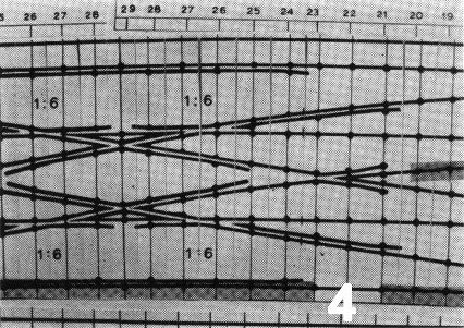
For complex units, use only the curved template method; even a scissors crossover may be curved successfully using several baselines (photo No.4). There is virtually no limit to the interesting formations that may be assembled using the curved template technique, and few modellers have yet adopted this method of adding a uniquely prototypical touch to their track.
Turnout wiring
All turnouts, from the most simple catch point to the most complex junction. require electrical connections if they are to function on an electrically powered model railway. The introduction of electrical feeds and the bonding of the groups of rails can be a most difficult operation if not carried out in the correct manner. As we do not wish to compromise the authentic appearance of our track, our permanent electrical bonds must be invisible. There are two types of connection to be made, firstly the bonding of the various groups of rails in the turnout itself, and secondly, the attachment of the electrical feeds, and the leads to other sections of the layout.
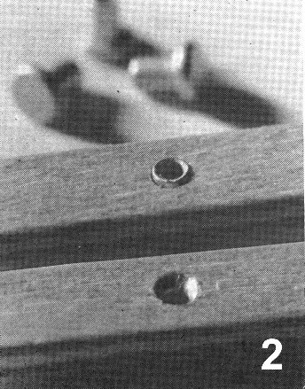
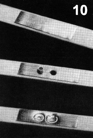
Turnout bonding tape (TBT)
For "internal" bonding, a pre-fluxed copper tape with heat resistant adhesive is applied to the base of selected timbers after punching, but before riveting, Its length is sufficient to cover the rivet group to be bonded, and these holes are re-punched to perforate the tape. During riveting the rivet base retains the tape which then forms an electrical connection between the rivets, and thus the rails, in the group. Permanent electrical bonding may be made using solder paint, and flux cleaned away afterwards with the glass fibre brush. The tape is too thin to affect rail levels during construction and laying, and as it lies on the base of the timber, it is completely invisible and protected from accidental damage when laid.
The TBT system is extremely simple and convenient to use and involves virtually no extra construction time, The integral nature of the connections eliminates the need for wiring and allows the turnouts to be used as units in conjunction with a system of wiring templates, which produce a standard wiring throughout the layout. [With the Editor's permission the Protofour wiring templates will be described in a subsequent article.]
Wiring Connector Strip (WCS)
This consists of a brass shim strip, prepunched at 8mm intervals to accept rivet shanks. It is used to provide the "external" connections and may be led from one timber or sleeper independently to another. The WCS is riveted to the timber base during the riveting operation.
For electrical feeds, the WCS lies in a slot in the underlay, in which it runs from the rivet base to a point outboard of the sleeper edge. By drilling through the WCS hole, and through the baseboard below it, a feed wire may be inserted from below until it appears above the WCS. whereupon it is soldered to the latter. The underlay is then replaced and ballasted. This system ensures that the feed connections are invisible, permanent, yet flexible and protected from damage. Even an accidental pull on the wires from below will place no strain on the track, nor will it affect the electrical bond, Connections below the baseboard may be made in any form required, by means of terminal strips or connector blocks, according to the wiring template diagrams.
A second use of the WCS is to provide connections between rails at scale rail joints. The 8mm spacing corresponds to the sleeper spacing at these points, and by connecting adjacent sleeper rivets by means of the strip, the rail can be cut through after laying without affecting the electrical continuity of the layout. The purpose of cutting through the rail is to provide expansion gaps, and to provide authentic wheel clicks as vehicles pass over the joints. The bonding is invisible after ballasting.
Turnout Operation
The final necessity for successful track is a turnout operating unit (TOU) which must have the following characteristics:
1. Simplicity of installation and maintenance.
2. Invisible operation.
3. Electrical insulation of the switch blades.
4. Switch movement in unison with minimal resistance.
5. Maintenance of correct fit of switch to stock rail when closed.
6. Maintenance of correct switch gap when open,
7. Maintenance of correct height of rails.
8. Suitability for use with all types of turnout.
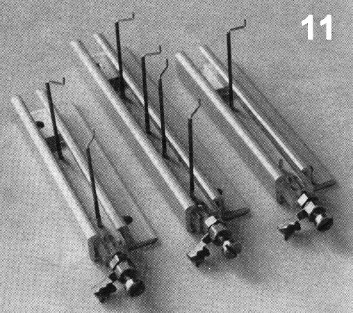
There are several ways of achieving these desirable characteristics, and the TOU to be described was designed for below baseboard installation and operation. It consists of a plastic bar sliding in an aluminium channel, the former incorporating two stainless steel tubes containing cranked nickel silver wires. The end of the bar holds an 8BA screw carrying a solder tag and two adjusting nuts for the attachment of power source rodding. The unit is secured to the 1/2in baseboard by two 5/8in round-headed screws, and the tubes will automatically position themselves flush with the top of the 1/8in underlay when installed.
The tubes reach the baseboard surface through two 1/4in or 3/8in vertical holes drilled outboard of the rails, and the cranked nickel silver wires are secured to, and operate, the switch blades. Later, the holes are covered by card strips with slots for wire movement, and ballasted.
The form of the unit is modified for catch points, where only one tube is required, and double slips, where four tubes are used.
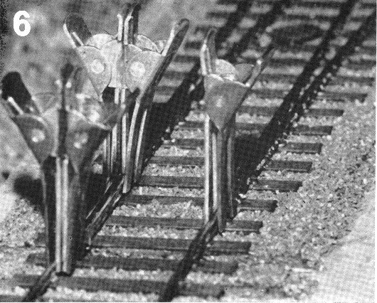
Attachment of the mechanism any mechanism to the switch blades involves adjustment of the throw and clearances. To facilitate this operation, the MRSG designed a simple switch blade Gauge Set.
This consists of three clips. The first clamps one switch blade to the stock rail, while the other two maintain the opposite switch blade gaps at the heel and toe respectively.
The appropriate wire of the TOU is soldered to the closed switch rail, preferably with "Wescolite", a strong, silver-based solder that is usable at normal soldering temperatures. (The flux, known as AFluxall", is excellent for all small soldering tasks and would be ideal for locomotive superstructures.) The clamp is then replaced by the gap gauges, and the second switch clamped and soldered. The TOU wires, being cranked, can be rotated to give the close fit required. The unit is now operational, and at any convenient time can be given a touch of epoxy adhesive at the joint of the wire and tube to maintain the correct rail height, which is held by the clamp until the adhesive has set.
Double slips are treated in the same way as standard turnouts, as both sets of switches at one end of the unit are operated together by a single lever. Two levers (and TOUs) thus control the four roads through the slips.
Stretcher Bars
All prototype turnouts have stretcher bars in either round or flat section material, which ensure correct spacing of the switch blades. Lever movement is transmitted via connecting rods. In model operations these bars, when fitted, are usually decorative only and in Protofour the correct switch blade spacing is ensured using the turnout operating unit in conjunction with the switch blade gauges. Protofour stretcher bars are made from 26swg (scale size) nickel silver wire to represent round section bars. The bar ends are accommodated in No 75 or 0.5mm holes drilled in the switch blades. One end of each bar is soldered in its respective hole; the other end has an insulating epoxy coating and is Araldited in place. The switch blades thus remain electrically insulated.
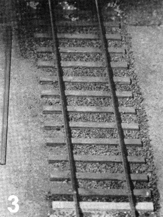
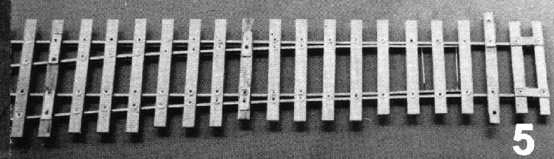
Conclusion
The photographs show the effects that are produced through the use of Protofour techniques. When it is considered that this appearance is obtained with the minimum equipment, the minimum use of time, and only modest expense, and yet produces thoroughly reliable operating characteristics, it can be seen that in the long term, the track will prove its worth.
Copyright - Model Railway Study Group, reproduced with permission.
Back to Magazine Index, Back to Site Index.
K Norgrove 25/04/03