This question came up on the E4um email list in a discussion of the Pocket Money Kit.Click on any photo for a larger version. |
|
Updated: 27 August 2003
This question came up on the E4um email list in a discussion of the Pocket Money Kit.Click on any photo for a larger version. |
|
"What does the brake gear look like? Is there some kind of offset Vee
hangers? I've checked out more photos than I care to remember and it looks to
me like one Vee bolted to the outer channel and the other to the inner channel of the
frame any enlightenment most welcome!
>
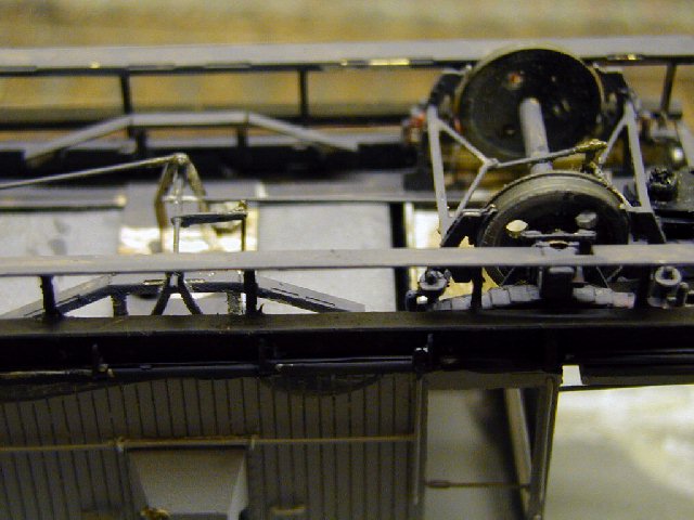
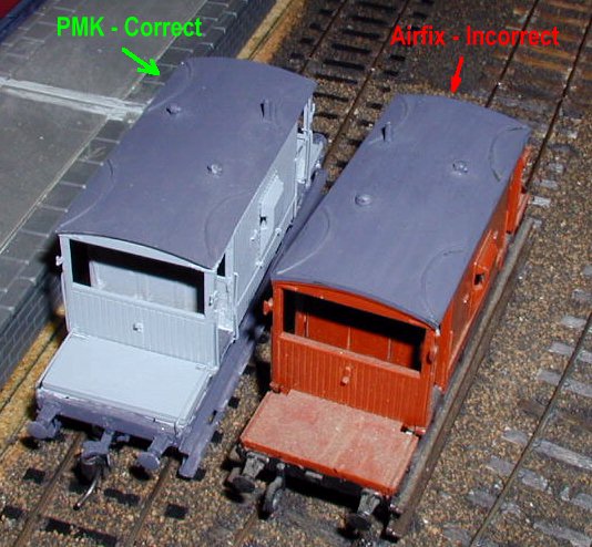
Correct in my opinion, the Vee hanger is on the
solebar on the side of the van where the hand brake pillar is, on the inner member on the
other side, this allows the pull rods and operating lever to be on the centreline, just
inside the one Vee hanger, and the crank connecting to the brake wheel to be vertically
under the pillar. the cross shaft is in the centre of the wheelbase. The side Vee
hanger is the only noticeable part. The exactoscale spring units include the Vee hangers
and you have to remember to cut one of them off. Note that since the kit does not
include the inner frame members you have to fix the inner Vee hanger to the floor in an
appropriate place. (But see below for some more detail)
I have looked at all the sources available to me at present, primarily books and articles by Roger Silsbury, Bob Essery, Don Rowland and Eric Gent. None of them supply drawings or photos that confirm or deny this opinion. Next time I find a brake van I'm going to have to get my knees dirty. Then you will get an update!
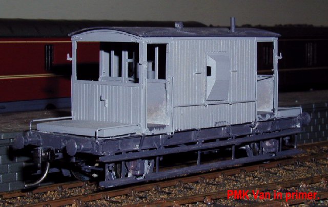
This picture shows, more or less, how I did it Available information indicates that the brake pillar and hence the side Vee hanger is on the opposite side (and end) to the stove and hence the chimney. |
Note, when looking at the van side on, if the chimney is on the nearside
it will be at the right hand end, if on the farside it will be on the left hand end.
Remember this when fitting the chimney, don't copy the Airfix/Dapol roof, they made a
mirror image!
|
| Also don't copy Airfix/Dapol and fit brake cylinders, most of the BR vans were piped only, the guard was expected to earn his keep. | |
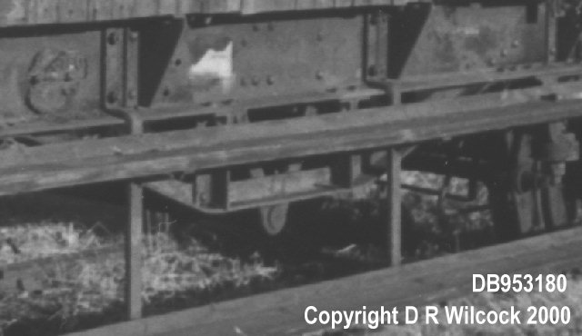
Discussion on the list produced suggestions that the BR Brake Vans did not have Vee hangers, Duncan Wilcock confirmed from his photos that the following vans definately did have Vee hangers;
No |
Lot |
Diagram |
Date |
DB953180 Whitemoor 1993 |
| DB953827 ZTV | 3129 | 1/506 | 58/59 | |
| DB952675 ZTV | 2606 | 1/506 | 1954 | |
| DB953180 ZTO | 2868 | 1/506 | 56/57 | |
| DB953890 ZTO | 3129 | 1/506 | 58/59 | |
| DB954199 ZTV | 3129 | 1/506 | 58/59 | |
| DB954471 ZTO | 3129 | 1/506 | 58/59 | |
| DB952737 ZTO | 2741 | 1/504 | 1955 |
I've been under non-Vee fitted vans and the pivot linking the brake column
to
the brakes is located behind the solebars with the links running directly
under the concrete blocks which fill in the gap between solebars. Which
makes the whole mech. almost invisible when viewed from normal angles.
The 'non Vee hanger' version has the pivot between and behind the solebars,
and the one I photographed (from underneath) had a linkage to one end only
with a return likage to the other wheelset running the full length of the
van. Thank god its only inches from the underside of the concrete infill,
and therefore almost invisible from trackside. It would be nice to see how
this mech. works!
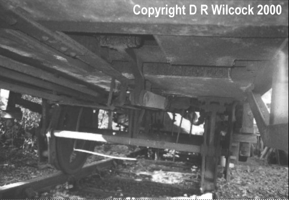
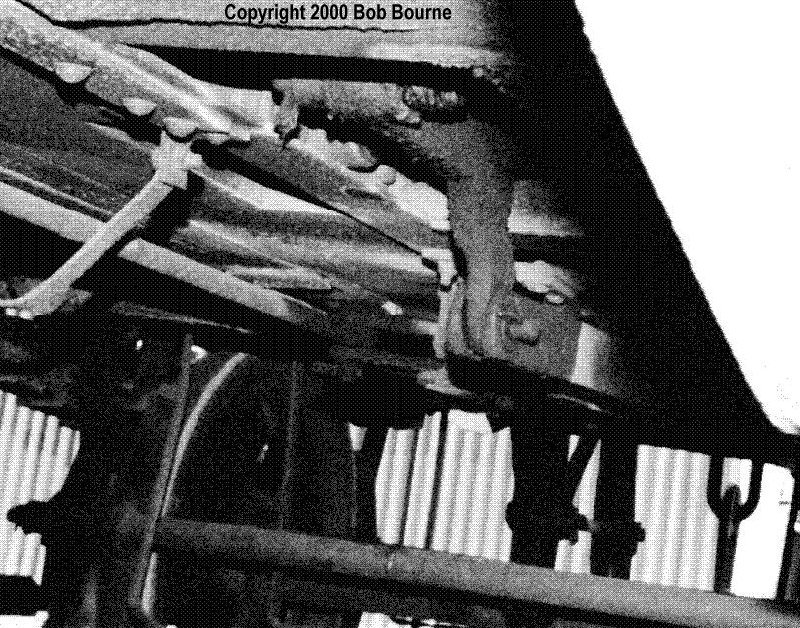
The underside of a non-Vee fitted van (preserved at Shackerstone). |
|
| The top print shows the pivot with the linkage to one end, with the return via what looks like a horizontal pivot attached to the underside of the frame. |
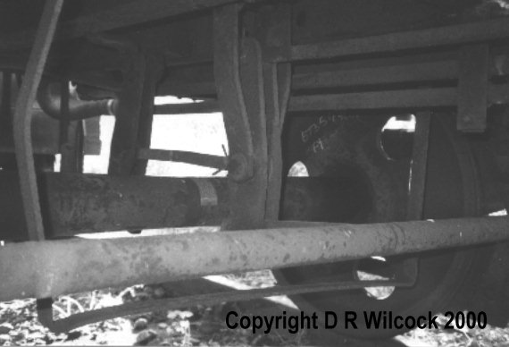
|
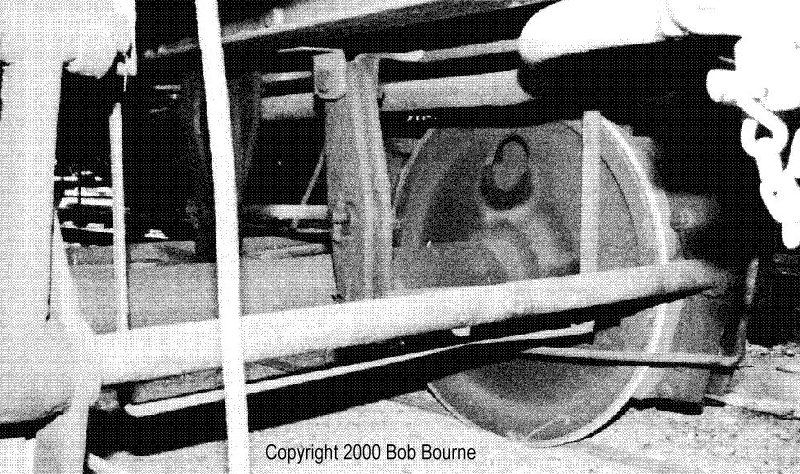
| The lower print shows the return linkage end....if you see what I mean. |
|
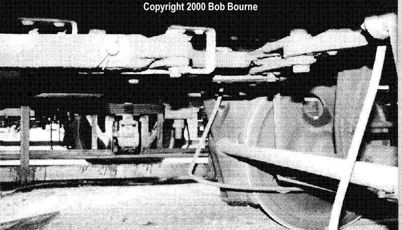
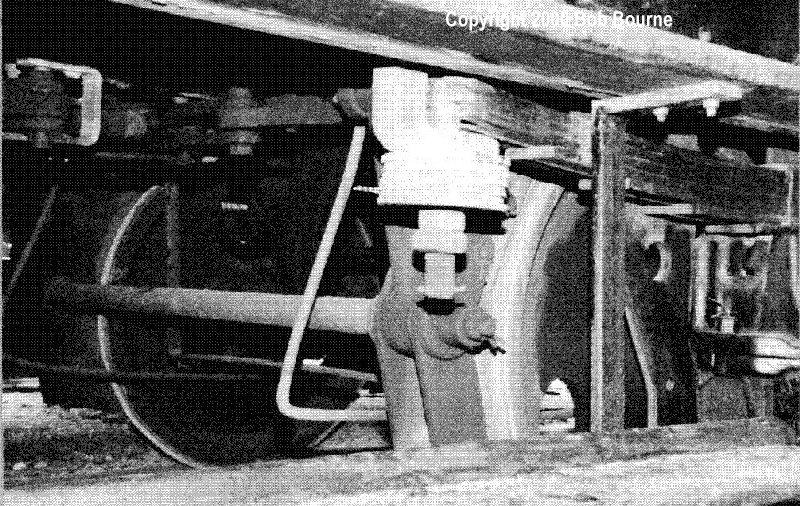
A few more photos from Bob Bourne confirm the brake arrangement for the non-vee hanger van and give a bit more of an indication of the compensating lever, they also show that an automatic slack adjuster was provided.
|
|
|
|
So it definately looks like my PMK kit needs some mods underneath, a bit more to come when I've got a round tuit.
Keith Norgrove, 14 February 2000.