Assembly continued
|
 |
|
The
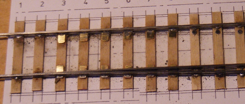
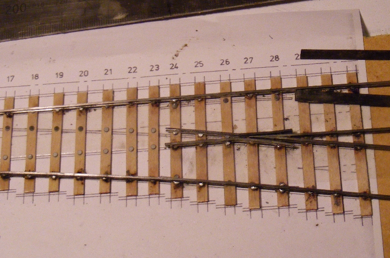
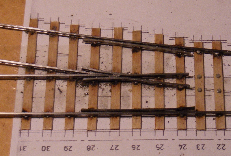
next part to fit is the other wing rail followed by the check rails
then the closures and blades, which I have made in one piece. The wing
rail is bent up as a mirror image of the first one, tried in place and
cut to length. |
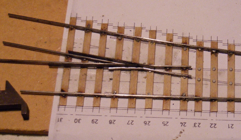   |
Check rails
|
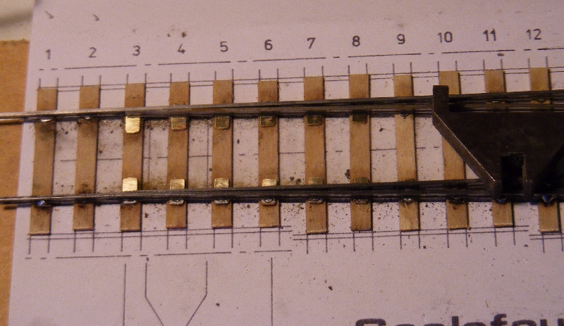
 The check rails are bent up to match the template. 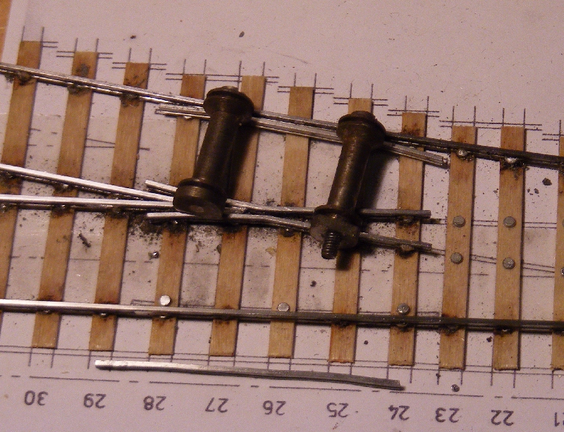 |
|
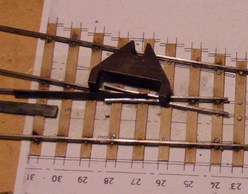
Then soldered in place using the check rail gauge, if you just have the one gauge solder one end at a time. |
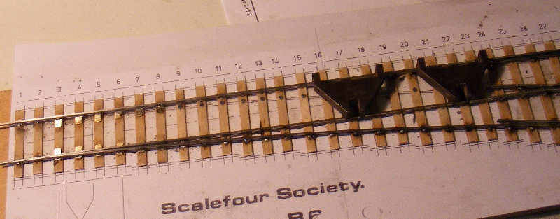
 Point BladesYou will notice I have skipped actually filing up the blades, for some reason I missed taking photos of this bit. I'll try and rectify next time I make a pair. Meantime you can check out Tony Wilkin's methods here. Then continue with a pair I made earlier. |
|
|
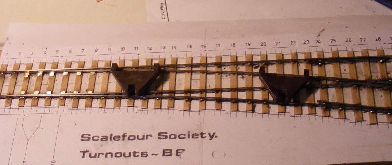
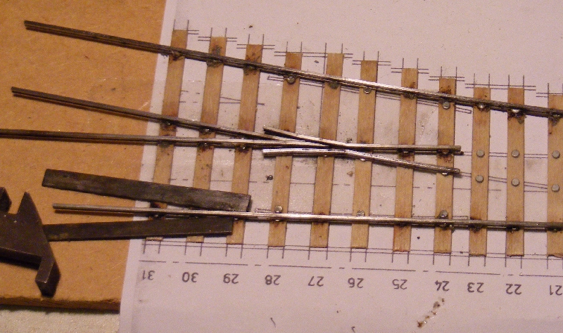
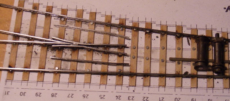
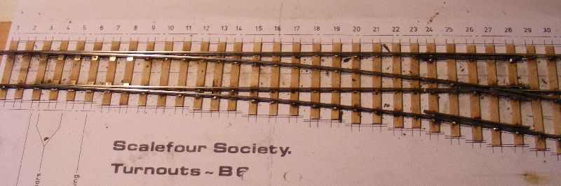 The turnout is complete. 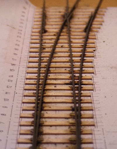 Slide baseplates from Bill Bedford were used and can be seen in the pictures. In this example I used the traditional group of 3 rivets under the vee as recommended inthe P4 Manual, normally I would use the Vee baseplates included with the slide baseplate fret. Use of these can be seen on my track relay page. All soldering used solder paint with the assembly being scrubbed clean under the tap when complete. The last two picture show the turnout after removal from the template and scrubbed clean. The scrubbing usually finds one or two unsoldered joints which can then be repaired. 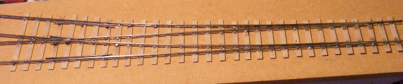 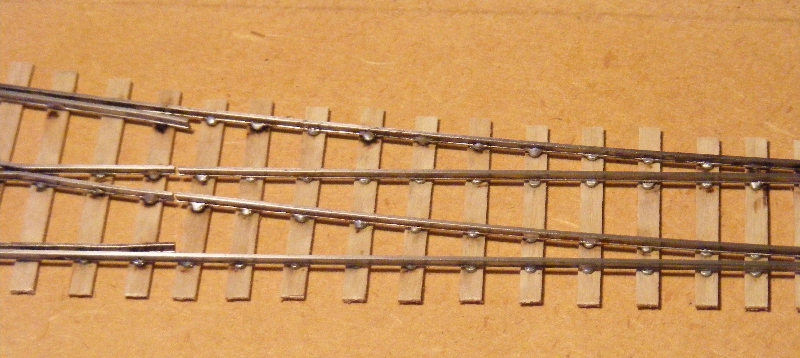 |