1. Remove existing couplers and fit KDs.
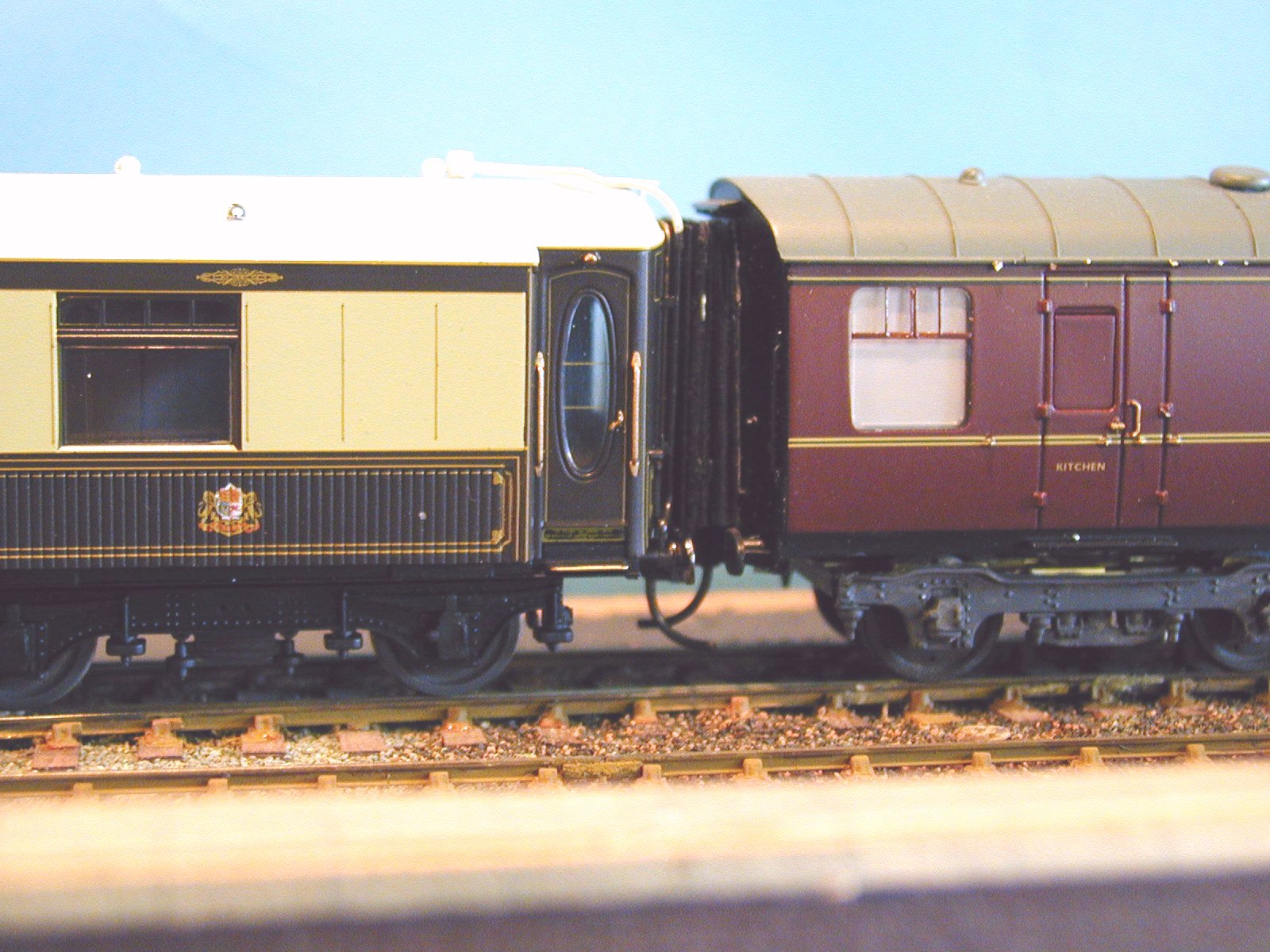
2. Remove existing gangway and fit MJT sprung gangways.
3. Change the wheels for P4.
4. Shorten the buffers so they are in the retracted position.
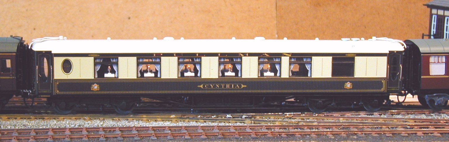
The complete coach, coupled
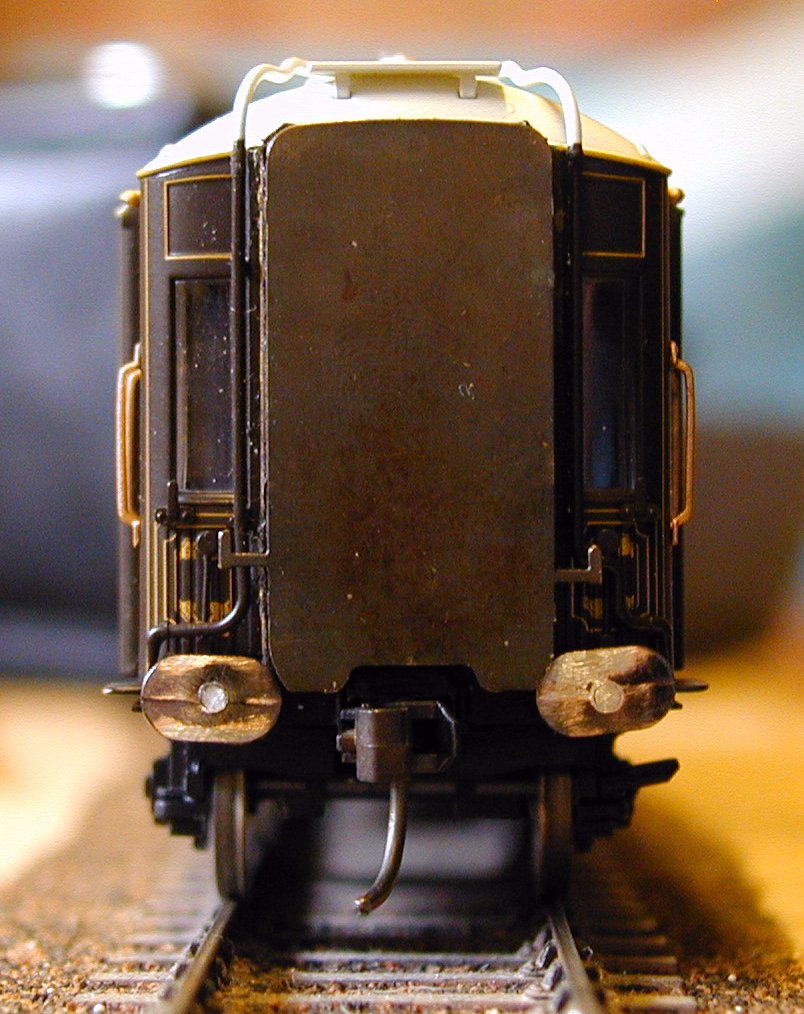
ends, end view and the underside.
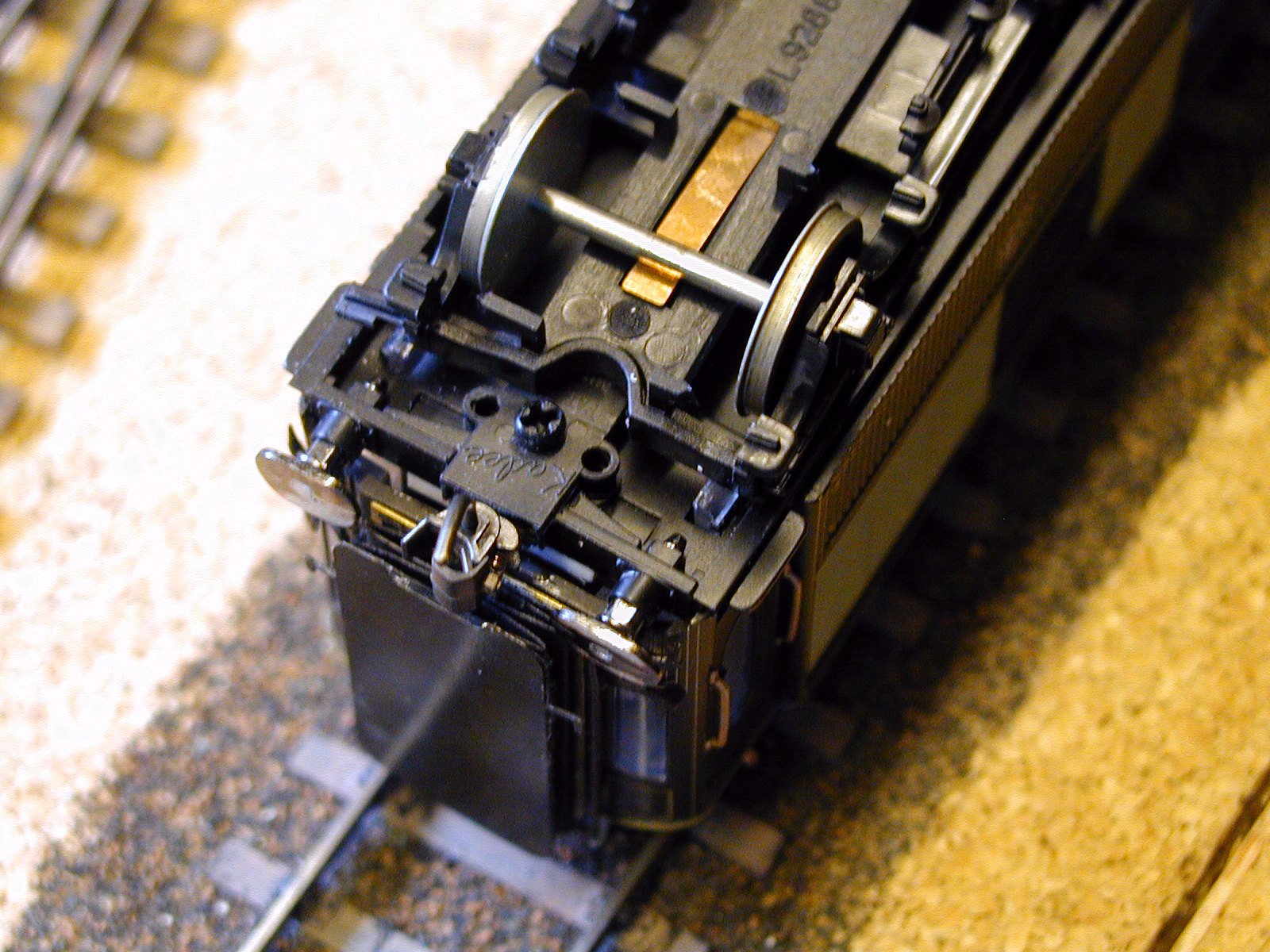
1. To fit the Kadee couplers the vehicle has to be dismantled as access is needed to the inside of the vestibules. The body is held on by clips at the centre and at each end, the end clips are part of the glazing and need to be eased out with a small screwdriver. The interior will come away with the body and should be released from the body by easing at the centre then pulling out. The body is then free and can be put aside.
The bogies are a push fit to the underframe and can be gently levered off. The work can all be done with the interior, chassis and bogies held together with the wiring but disconnect it if you think it makes it easier. The Hornby couplings can be removed by removing the securing plate, do this if you think you may want to put them back. I just left the securing plate alone and cut them off. To fit Kadees the centre of the buffer beam must be cut away and the Kadee draft gear box bolted to the floor. While doing this gently push out the buffers from the back and put buffers and springs in a safe place. There is a strange thin 'knockout' in the floor just where you need to drill and tap this needs to be glued in place with plastic weld and a piece of 40 thou plasticard fixed to the top of the vestibule floor to provide enough material to drill and tap into, the original floor is very thin. I have used the KD42 which matches to the rest of my stock, the KD58 is closer to scale size and could be used just as well, they are a bit more fussy on height matching.
2. While the plastic weld is hardening ready for the drill the body can be worked on. The gangways are made of soft plastic but are far to stiff to allow contact in operation, take them off. They are just glued to the end and will come off if a sharp blade is worked around from the inside. Make up a pair of MJT LNER/Pullman gangways and fit in their place. The ends should be chemically blackened before assembly. I reduce the folded paper by one fold as I find that, assembled as supplied, the contact pressure is high and results in derailment, one less fold and they just rub together gently. For coaches normally in the middle of a rake I fit the outer cover smooth side out, those sometimes used at the end can have the detail side out but it needs to have the corners rubbed of the panelling to prevent it catching on the adjacent one.
3. Change the wheels for a set of Branchlines, Branchlines because they are solid metal and insulated one side only hence no change is required to the lighting circuits. The bogies are flexible enough to self compensate so no need to fit sprung bogies. When changing wheels you have to be very careful not to break the end steps off the bogies, they are very fragile and in the way. The brake shoes will foul the new wheels, you have to cut them off and will need to make up new ones if you want them.
At this stage you can clip it back together and give it a test as the buffers can be replaced without dismantling anything.
4. The buffers as supplied are to long for use with Kadees, OK
for the ends of the rake if you use different couplers to the loco. I mucked up
the first buffer so that ended up as fixed retracted. I then changed the
technique and the other three are retracted and still sprung. Cut the head off
close to the back of the head, ie leaving the spindle attached to the shank and
the boss on the back of the buffer. Drill a 1.2mm hole in the centre of the
buffer, the boss locates it in the chuck while doing this. Superglue the head
back on the shank , check that the orientation is correct with the flats on the
shank which should be horizontal. When set file off the protruding spindle and
refit the buffers. You now have retracted, but still sprung buffers.
Copyright Keith Norgrove.
Last revised: March 21 2008