Bridgenorth 2007, Detail photos by Rod Cameron.
"Since there seems to be an interest in point rodding etc at the moment,
not least from me, it was convenient that my travels yesterday took me
past Bridgnorth on the Severn Valley Railway where I stopped off to have
a look at the ground-level infrastructure.
No trains running, at least not at this end of the line, due to the damage caused by the flooding earlier in the year.
These photos originally posted on RMweb by Rod, his descriptions in plain text alongside supplemented by mine in italics.
|
|
1.
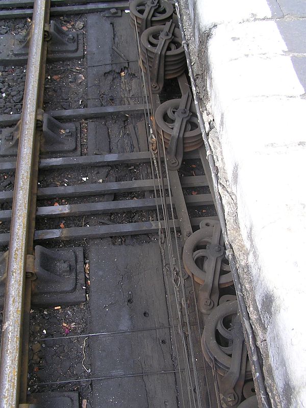
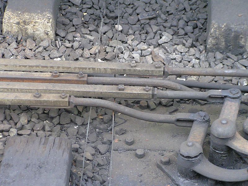
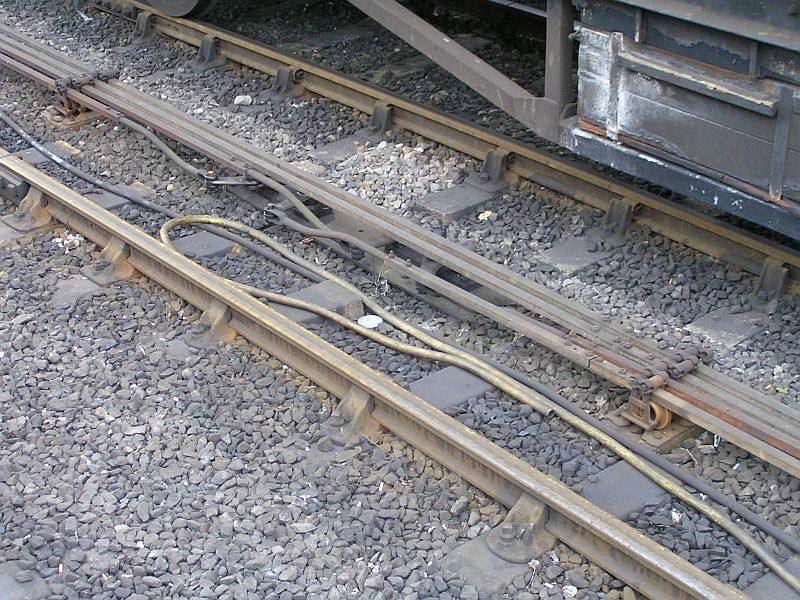
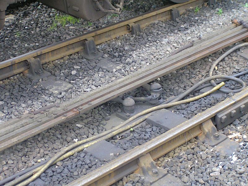
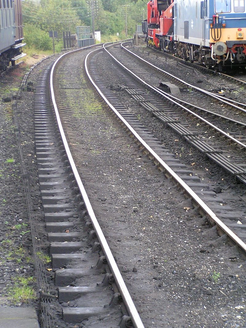
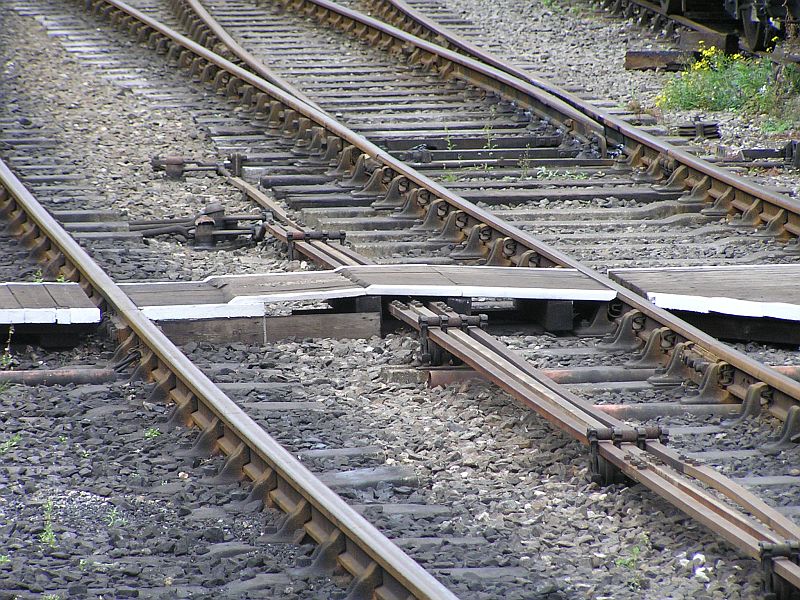
Bridgnorth has a signalbox on the platform, so first stop looks at
how the rods and cables emerge (couldn't get better views due to a train
stabled in the opposite platform) and how they are then cranked at
right angles in the six foot. Note also the signal cables routed
immediately along the platform face by pulleys:
NB. The signal wires (7
strand galvanised steel) have flexible steel cable inserts to go round
the pulleys, the 7 strand wire quickly breaks from fatigue if flexed.
The eye joints between the two types of wire can be seen..
Note also the cross track rodding rubbing on the underside of the rail, very much to be avoided if the line is track circuited.
|
|
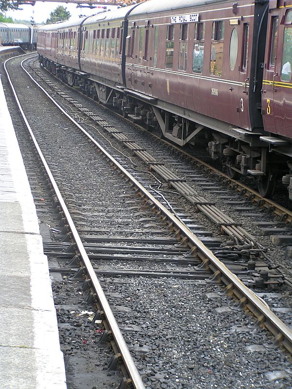
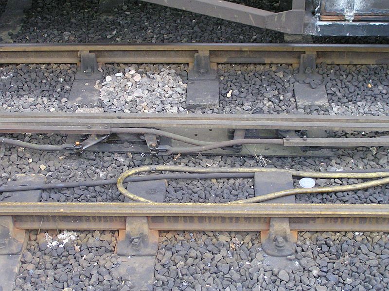
2
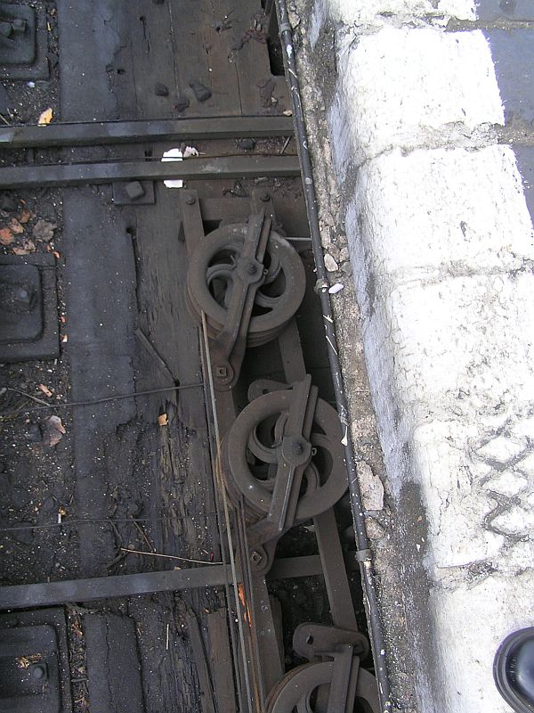
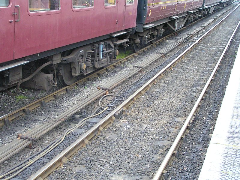
More of the above, note the pulley frames are mounted on a couple of lengths of channel rodding.
Also the electric cable cleated to the platform face.
|
 | 3
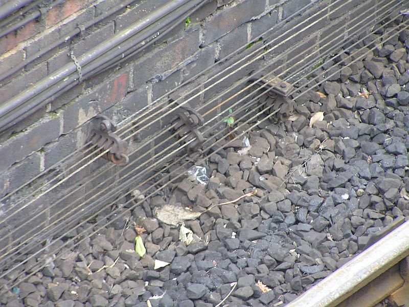
The signal wires running along the platform face. |

|
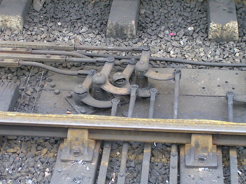
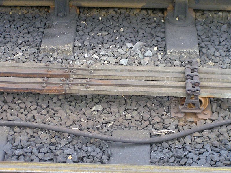
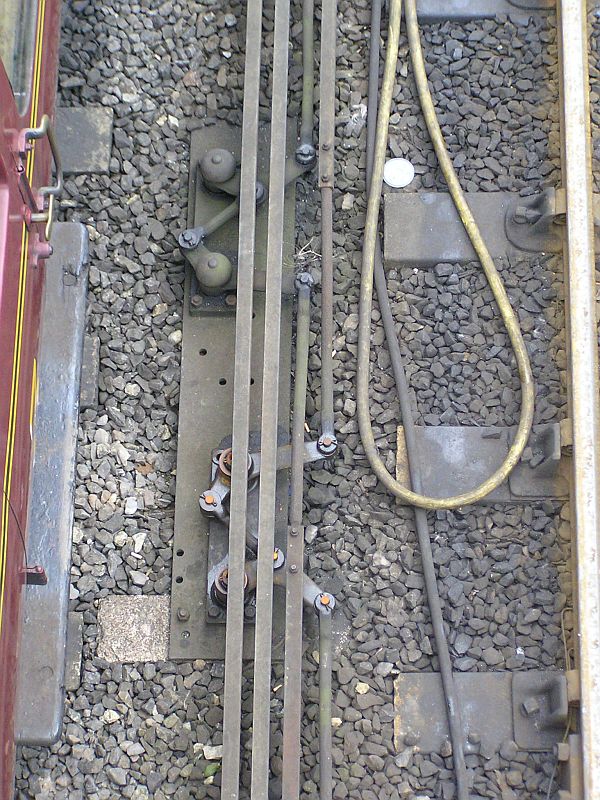
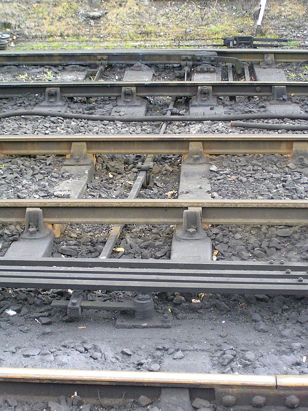
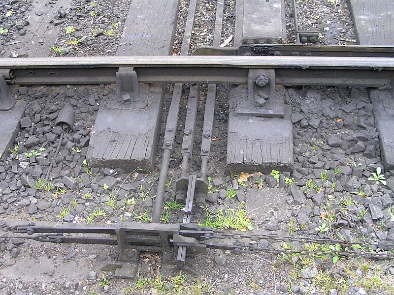
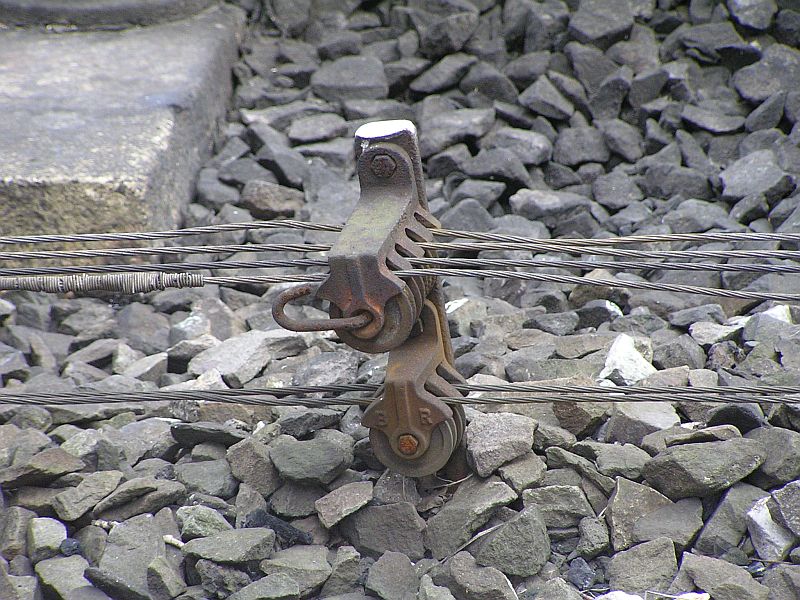
4
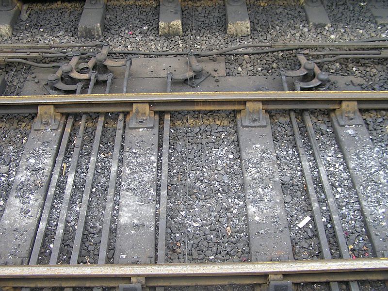
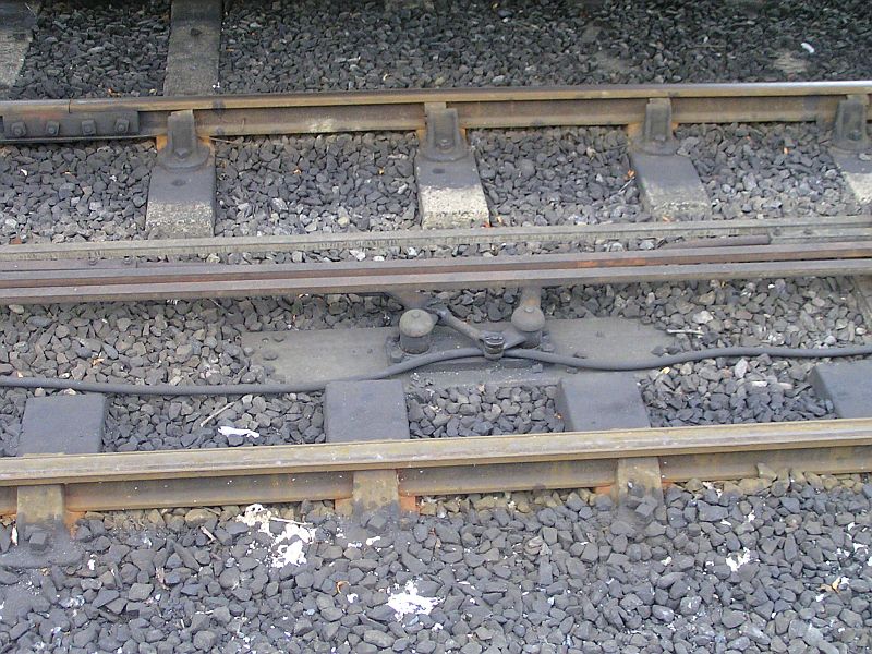
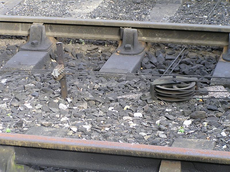
Rodding stool detail
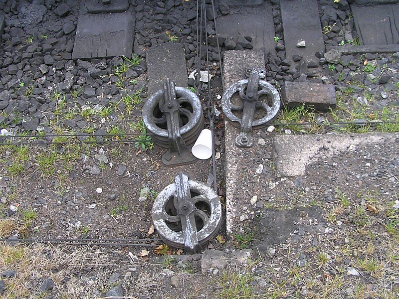
, (and how they are then cranked at
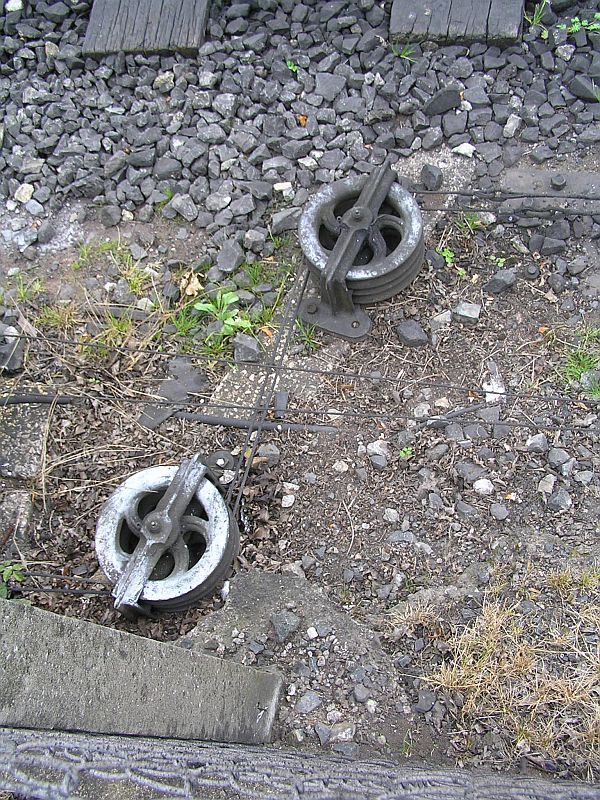
right angles in the six foot.).
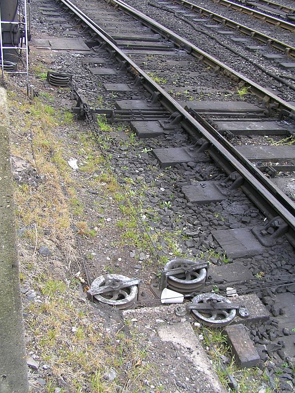
Note use of low and high accomodating cranks (cranks with curved arms) to suit the close spacing of the cross track rods.
|
 | 5 |
 | 6 |
 | 7
|
|
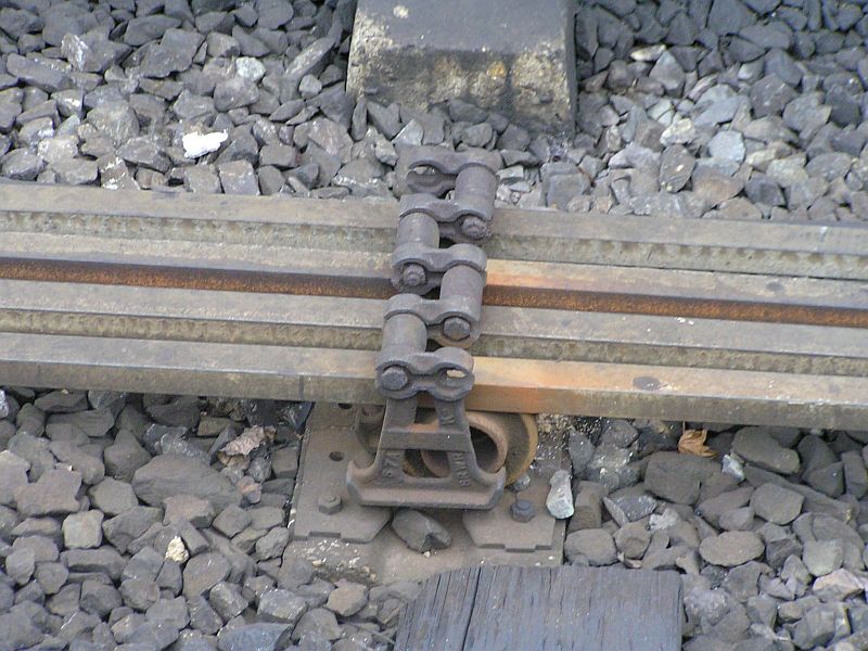
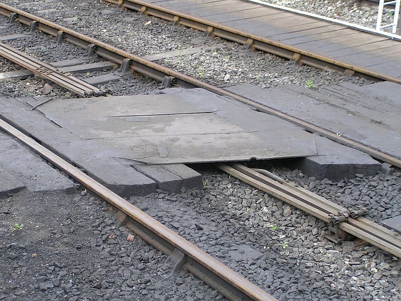
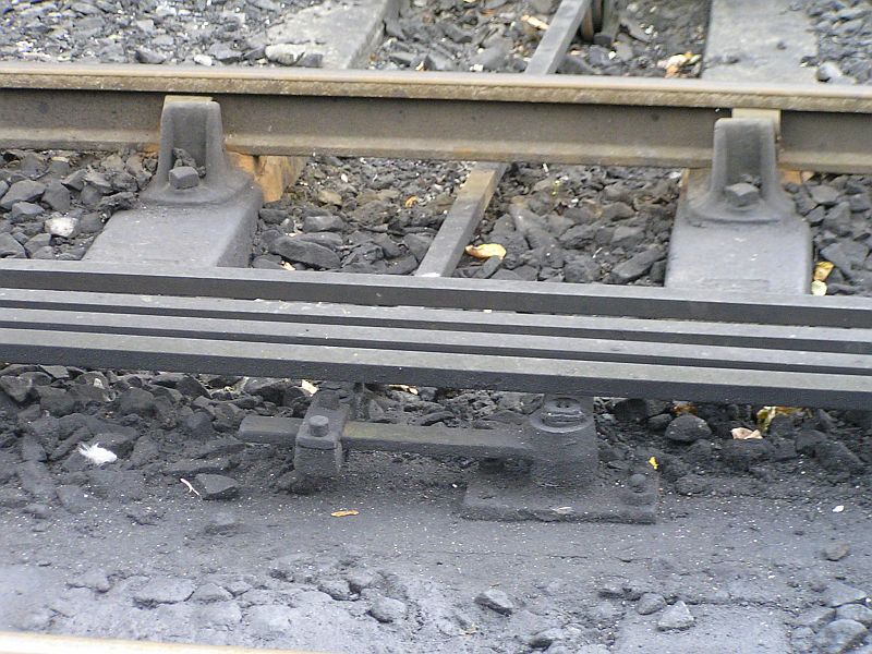
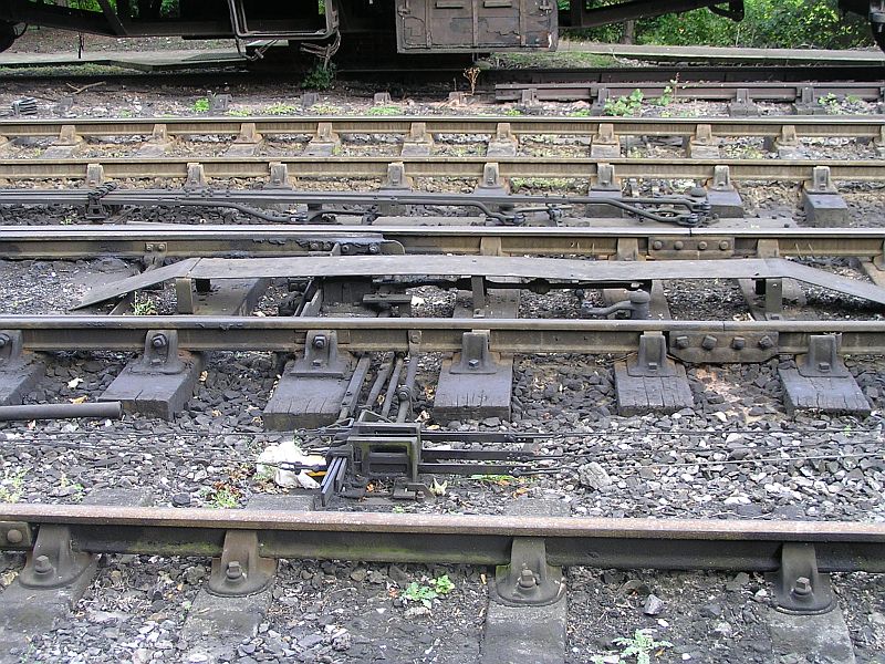
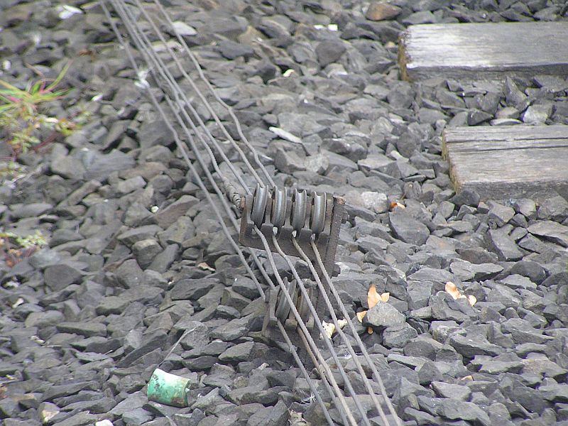
8
The first compensators in this run are under the footbridge (just visible at the top of the photo):
|
 | 9 |
 | 10 |
 | 11
Two of the four rods are compensated simultaneously, presumably because that is their common neutral point
.
|
 | 12 |
 | 13
Handy that the footbridge was there for an overhead view
|
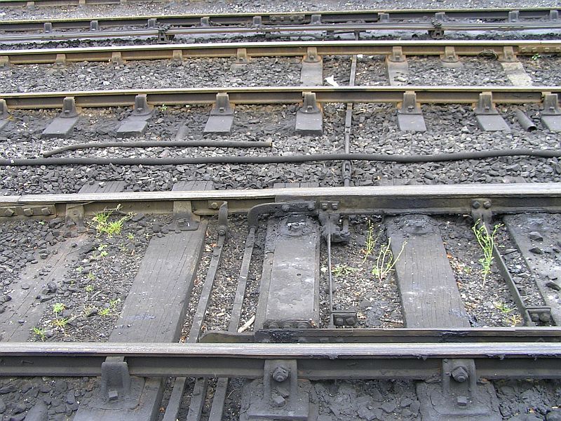
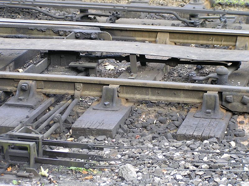
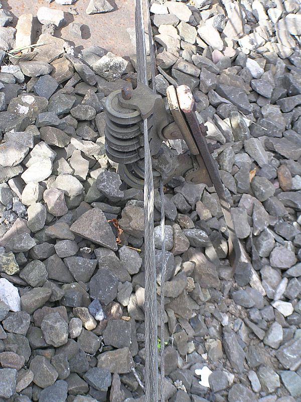
 | 14
The other two rods were compensated individually a few yards further on
|
 | 15 |
 | 16 |
 | 17
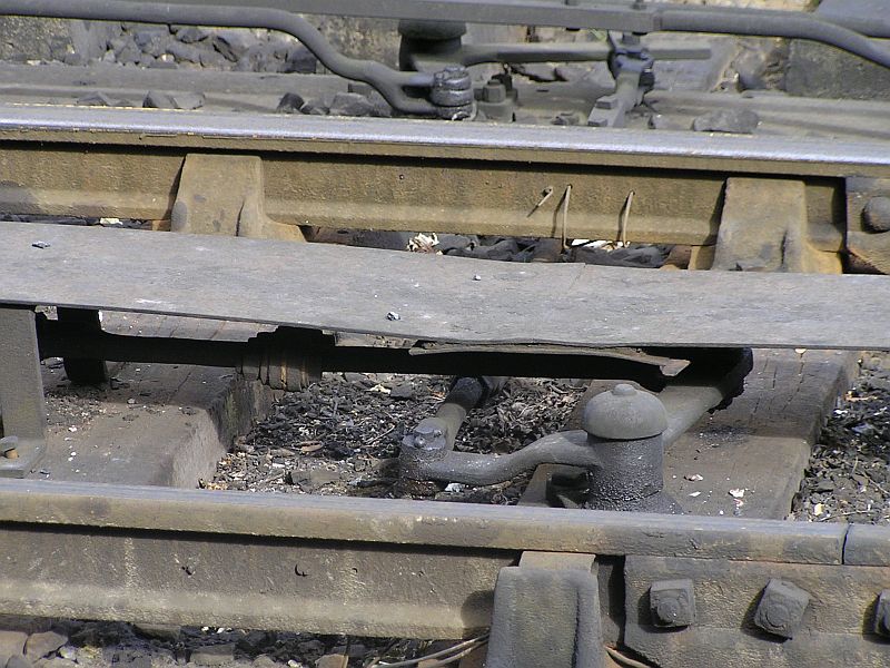
This compensator is hidden under a walkway. |
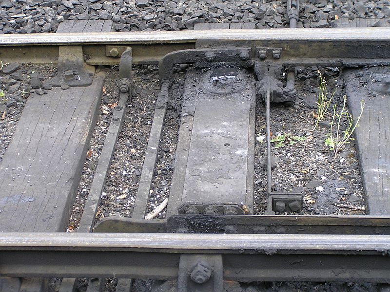
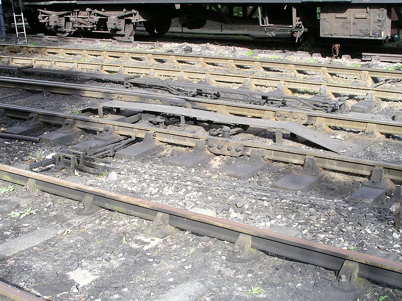
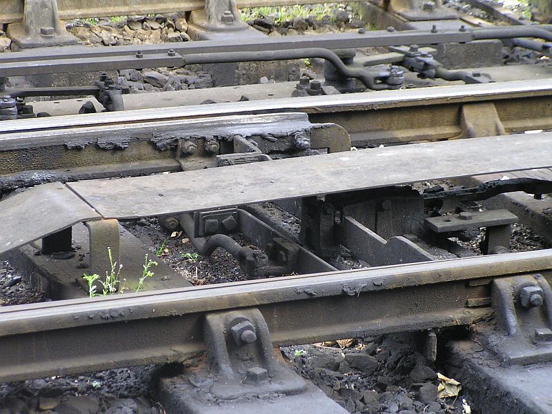
 | 18
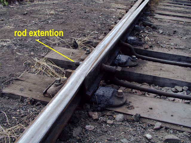
Here one of the rods has a 'branch' cranked off to operate one point
of a crossover; the 'main' rod will continue to the other point in the
pair so that both points are operated together by the same lever.
NB.
The drop lug connecting to the crank from the far rod cannot be seen in
the pic but the bolts holding it to the rod are just visible in the
next pic. |
 | 19 |
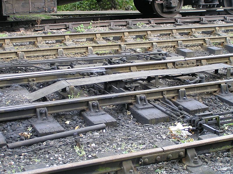
 | 20
View from the other side (and no I didn't walk across the tracks  ) showing the connections to the point blades. ) showing the connections to the point blades.
Note, the drop lug connection from the main rodding run can be seen at the top of the picture.
The switch extenders to connect the detection rods are also clear in this picture. |
 | 21 |
 | 22
Detail wiew of the two slide detector, no facing point lock so third slide not required. |
 | 23 |
|
24
|
|
25
Also note the locking bars preventing inappropriate pulling of
signals for a given point condition. I thought this sort of thing was
done in the locking frame in the box, or is this an additional
safeguard?
These
are known as point detectors and supplement the locking in the frame to
prevent signals being pulled off if the points have not responded to
their levers because of rodding damage or maladjustment. The three
detection slides, one connecting to each switch toe and one to the
facing point lock have to be in alignment for the signal slides to be
pulled through.
|
|
26
Facing point lock (FPL) and cover (also with integrated signal wire locking bars)
As above.
|
|
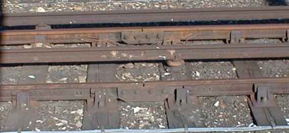
27
This
close up shows, at the top, the two adjusting cranks, for the point
drive on the left and for the facing point lock on the right.
Also
the facing point lock, lock stretcher, switch extension to connect the
detector, the three rods to the detector and the tie bar holding the
detector frame fixed in relation to the stock rail.
|
|
28
More
detail of the adjusting crank at the top and the final drive crank for
the lock, the latter has unequal arms to increase the throw for the
lock bolt.
|
|
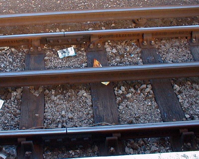
29
Here the detail of the drive and lock stretchers and the far side switch extender can be seen more clearly.
|
 | 30
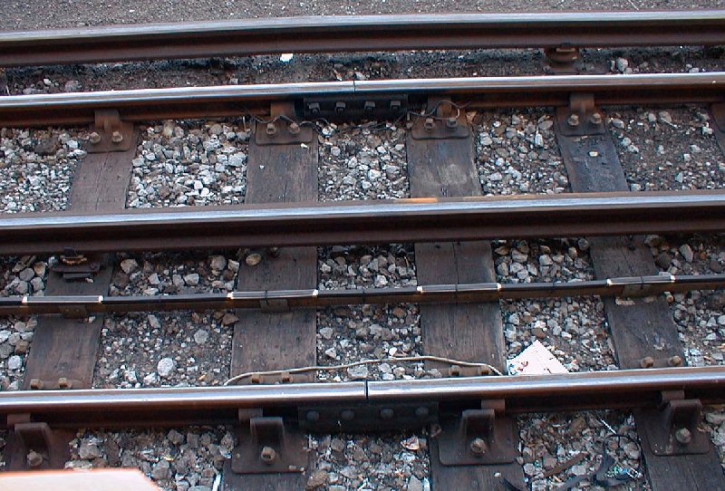
Here another walkway crosses the rodding run.
The
back rod, connecting the turnout in the picture, is badly bent, might
have had a run through, but anyway certainly in need of TLC. |
|
31
A few shots of signal cables and how they are carried and made to change direction
.
NB. These normally called signal wires.
A
joint is visible in the nearer top wire. The wire support pulleys are
the standard ones for straight runs. It looks as though an emergency
repair was done, a long time ago, to the top one using a length of wire
instead of the axle bolt
|
|
32
This
is a bit of an oddity, the pulleys installed upside down and badly
aligned. There is signs of wear on the pulleys though that
suggests that the wires try to rise when in tension.
|
|
33
These
are the hinged wire pulleys used where the wire run takes a gentle
bend, in this case the stake seems to have bent over to the point where
there is practically no deflection in the wires.
|
|
34
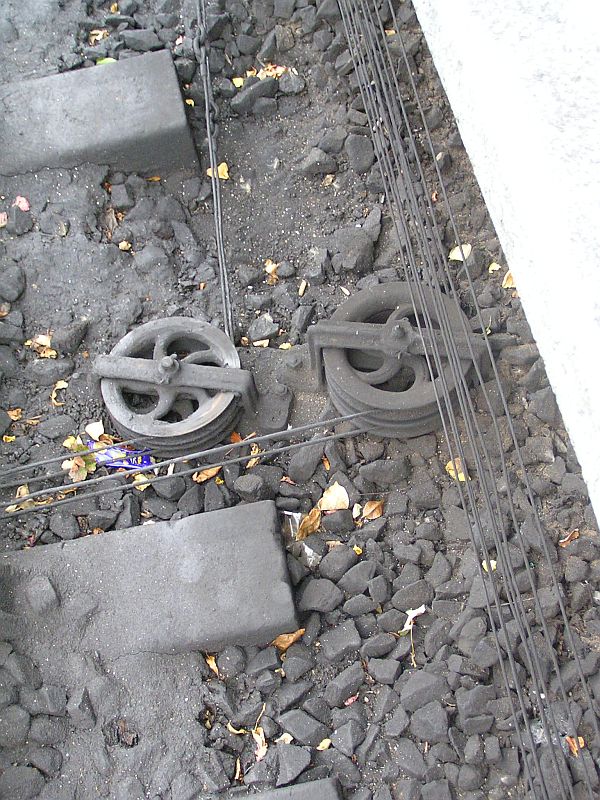
Here a pair of wheels on a concrete stool with 4 wires continuing on.
|
 | 35 |
|
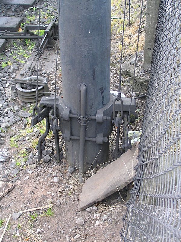
36
Here
the base of a bracket signal with 4 wire cranks, 2 of the
wires can be seen coming via the detector slides on a nearby point, the
other two wires are hidden behind the mast.
|
|
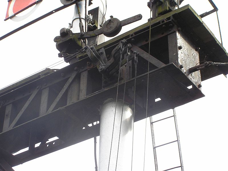
37
And the top end of the same 4 wires showing wire cranks and the balance weight for the ringed arm.
|
 | 38 |
 | 39 |
 | 40 |
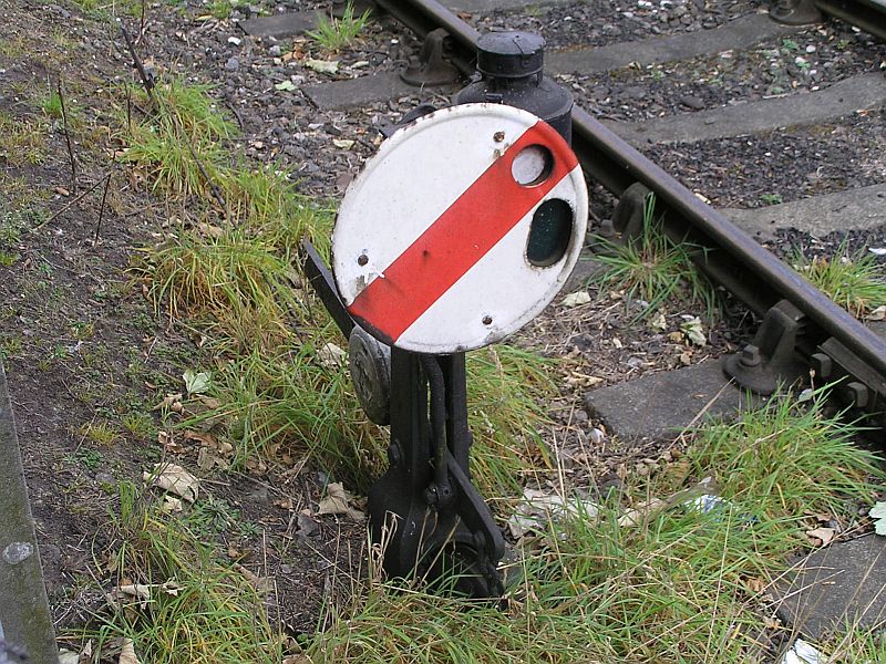
| 41
Ground shunt signal in the off position, front |
| 42
side, |
| 43
and rear. |
 | 44
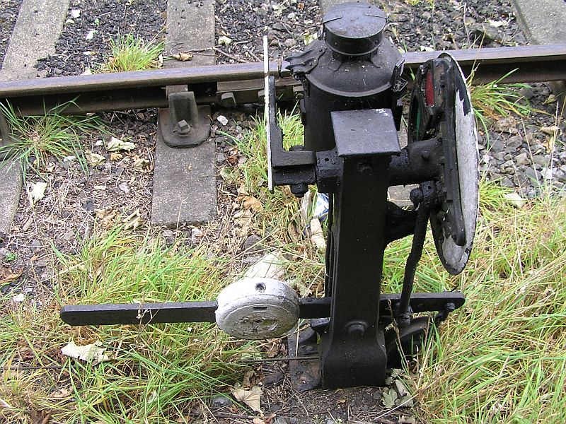
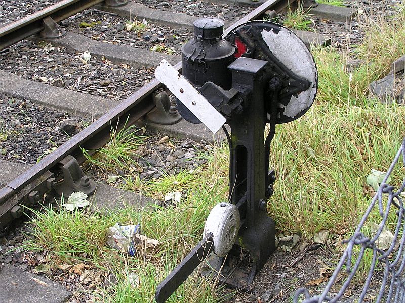
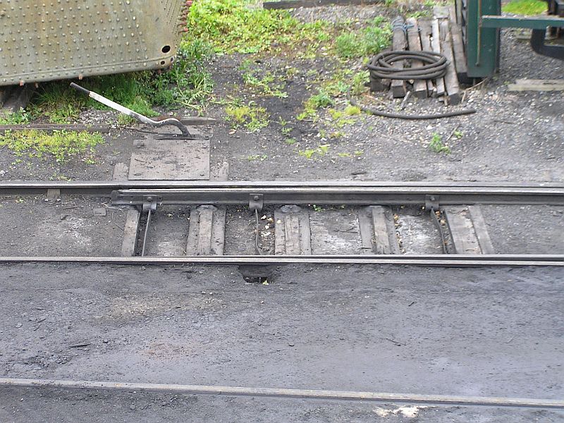
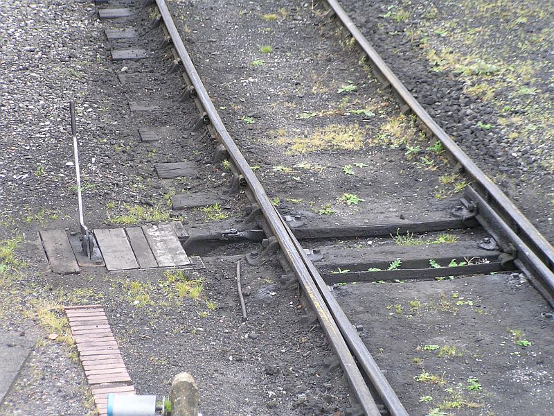
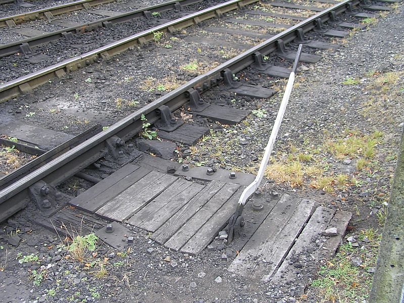
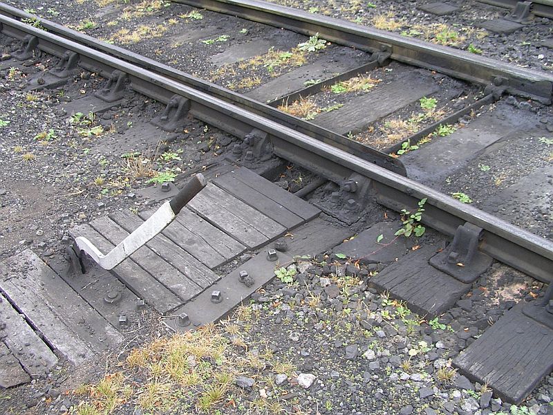
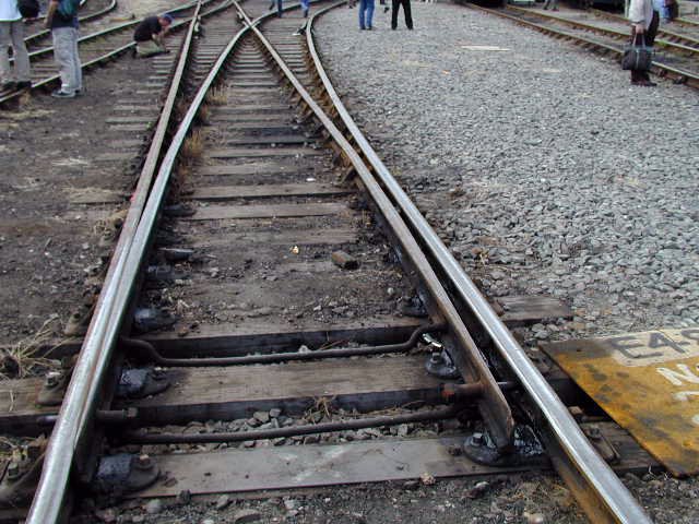
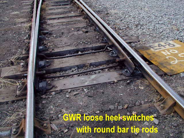
And finally some details of hand operated points and their levers in the yard |
 | 45 |
 | 46 |
 | 47 |