The problem |
|
|
The idea here is mainly to let the photos do
most of the work so I'll just put notes in here where it seems useful.
Clicking on any photo will bring up a bigger version 800 pixels wide,
in some cases where it aids clarity there is also a bigger version
reached by clicking on 'extra large'.
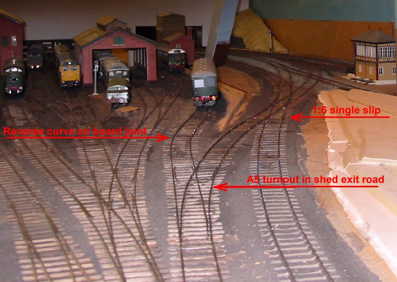
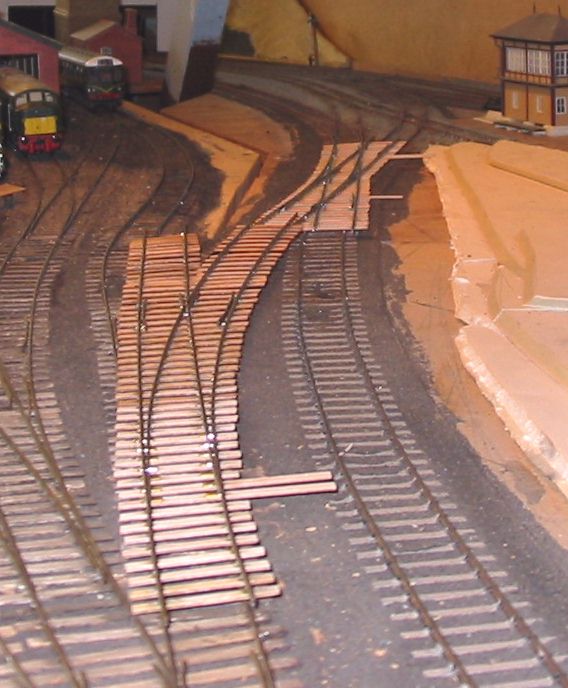
Pictures 1 and 2 show the scene before the start of work. The offending track is the second from the right, heading out over the single slip to join the main line by the signalbox. The siding with the parcels car on also has a nasty reverse curve right on the board joint and it is hoped to improve that as well. |
 1 1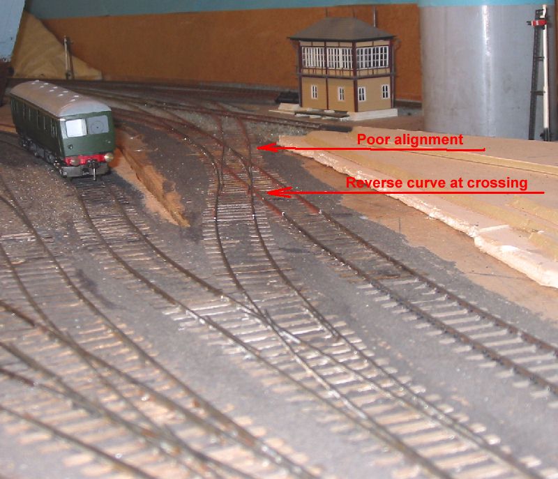 2 2 |
Planning the Solution |
|
|
Templot was used to draw out the new alignment
on a trial and error basis.
First
I produced a section of plain line of an appropriate radius to fit the
site., printed out this was overlayed on the layout and an estimate
made of the amount of change needed for a good fit. The third attempt
worked. I then overlayed a left hand turnout on this curve keeping the
main road to the radius already established.
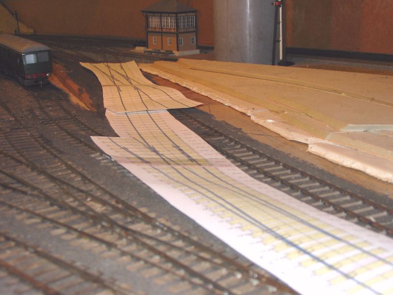
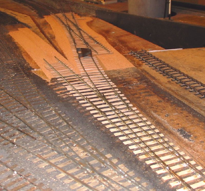
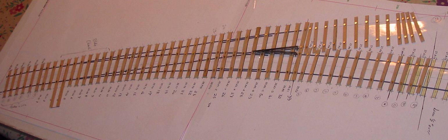
The existing single slip was 1:6 and the alighment had never been correct, so I printed out a 1:7 and tried that, this had an equally bad alignment in the opposite sense where it fitted to the existing tracks at the signalbox end, so I tried again with a 1:6.5 and this proved to be what was required. Pictures 3 and 4 show the resulting printouts laid out over the existing track. |
 3 3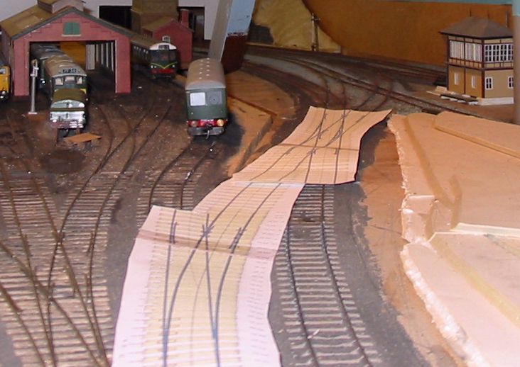 4 4 |
Building the new track |
|
|
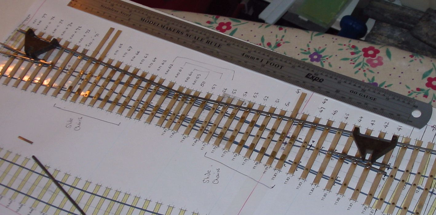
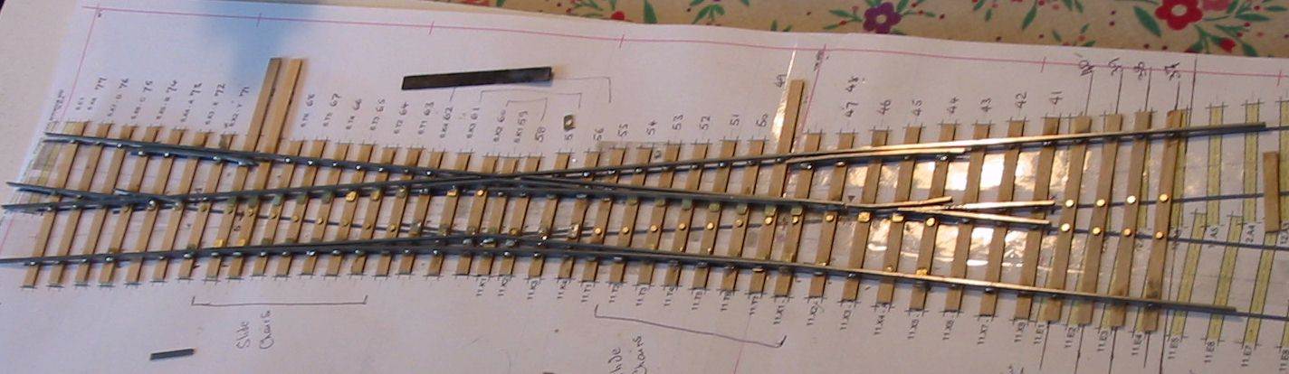
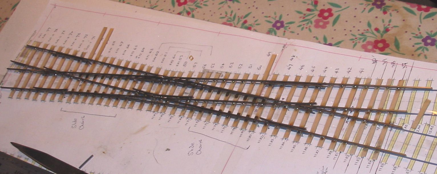
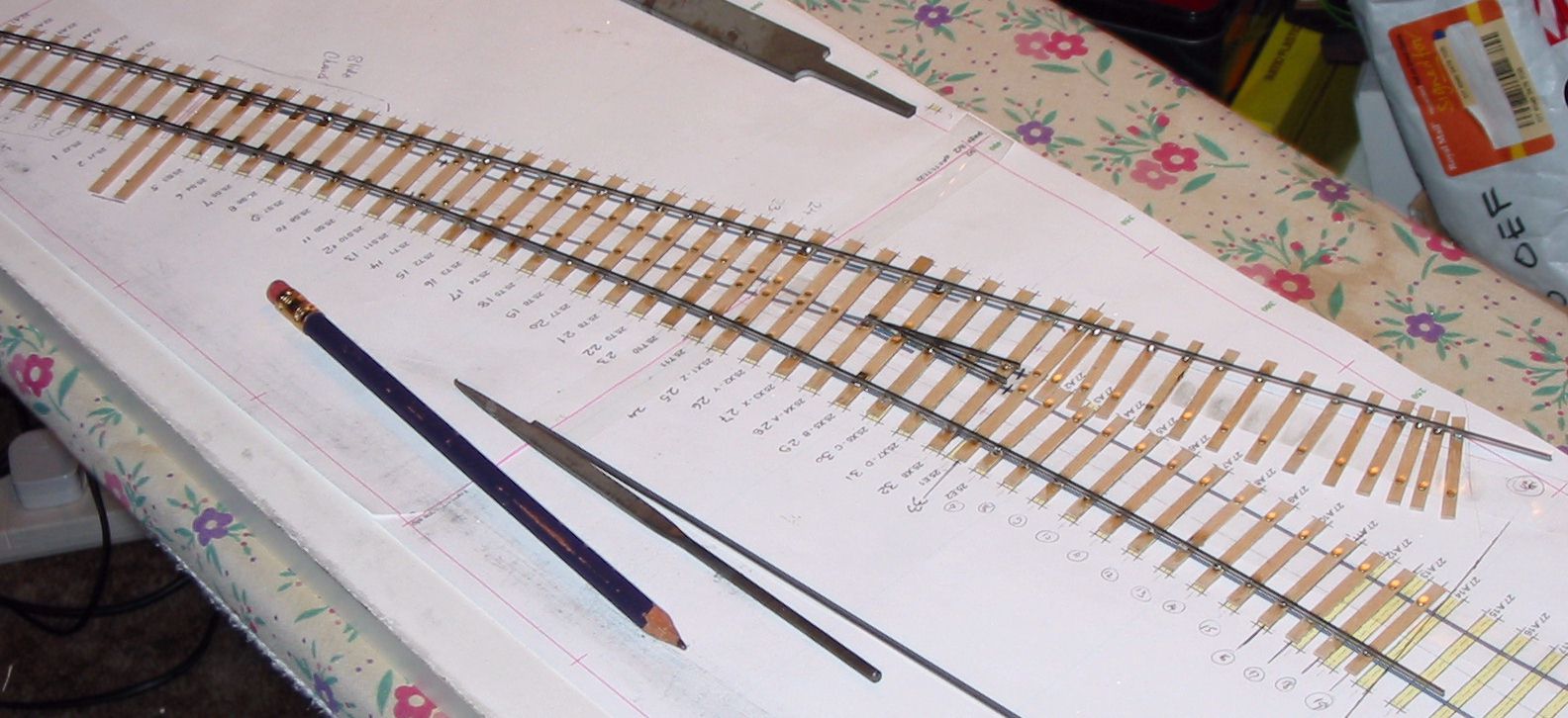
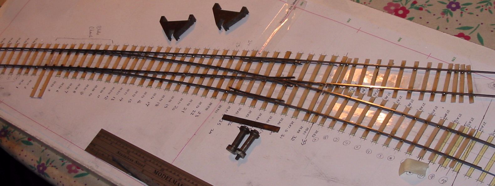
I decided to build the new track before
disturbing the old so I could confirm that it fitted properly before
taking an Engineer's possession.
To match the existing track I used traditional ply and rivet construction although my stocks turned out to be low and I had to buy sleepers,and rail from Scalefour stores at the AGM. Pictures 5 through 12 show the sequence of building the single slip and 14 to 18 the curved turnout. I followed my normal practice of using two offcuts of timbering to make a jig for the vees prior to fixing the timbers in place to continue the construction. The point and splice rails are soldered together upside down in this jig. Slide and vee baseplates from Bill Bedford were used and can be seen at strategic locations in the pictures. All soldering used solder paint with the assembly being scrubbed clean under the tap when complete. |
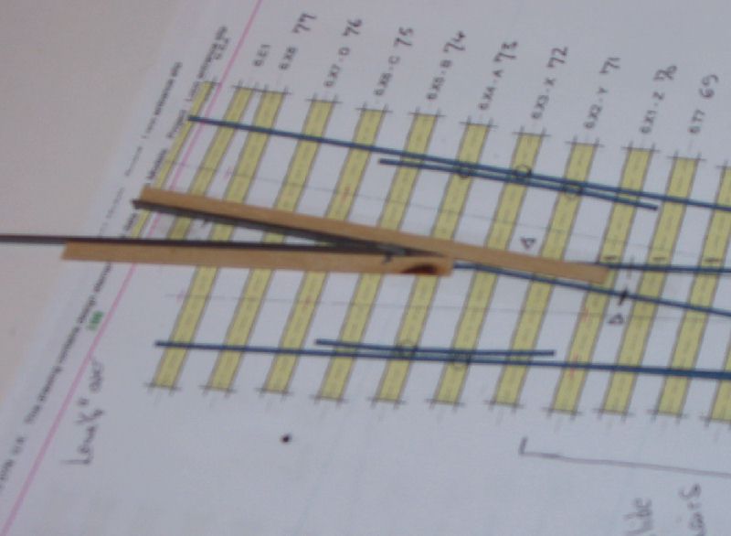 5 5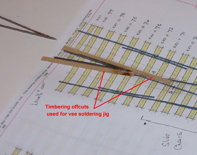 6 6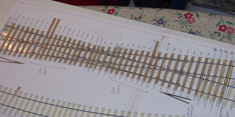 7 7 8 extra large 8 extra large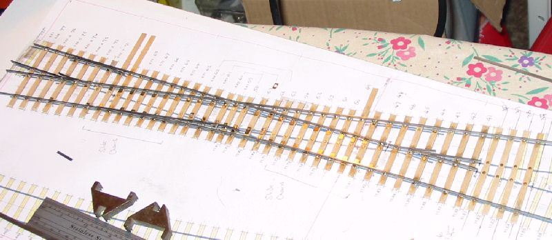 9 extra large 9 extra large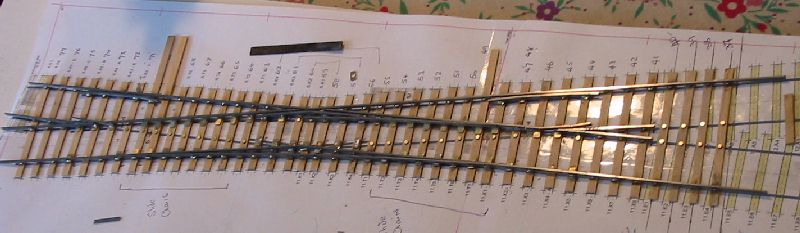 11 extra large 11 extra large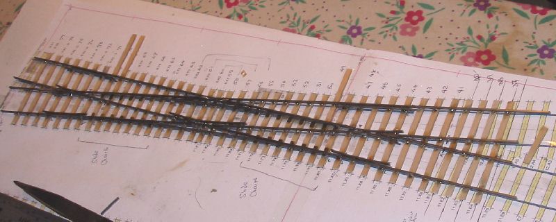 12 extra large 12 extra large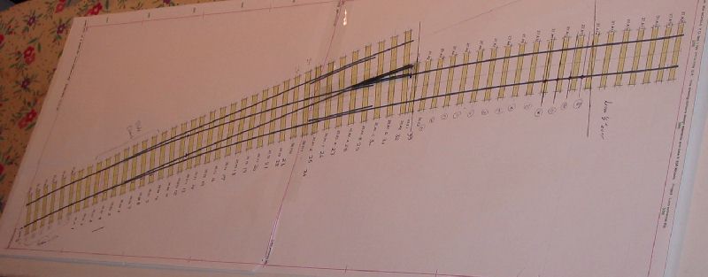 14 14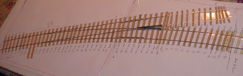 15 extra large 15 extra large 16 extra large 16 extra large 18 extra large 18 extra large |
Site preparation |
|
| Picture 19 shows the completed track
superimposed on the old and can be compared to picture 4. Satisfied
that all was well I got stuck in to site clearance. My track is all stuck to the cork with white glue, originally I used the usual DIY brands which are hard work when lifting track is needed. Now I use children's brands such as that from the Early Learning Centre, designed to wash out of kids' clothing they are much easier to lift should it be needed. In this case I think I had some of each to deal with. Since none of the track was wanted I first unsoldered the rail from the rivets leaving just sleepers and ballast. For this unsoldering I have found my RSU the quickest method. The rails were left in the one siding laid with C&L track as it will easily lift out complete when soaked, the adhesion of the glue to the plastic sleepers is much less than for the ply. The formation was then soaked with water and as the glue softened the sleepers and ballast were scraped up to leave a clean formation. This process uses a combination of chisel and scraper and is something of a struggle. A little over half the area of cork became damaged excessively and was lifted as well. Picture 20 shows the result with an area of clean board and another of existing cork underlay. Picture 21 and 22 show some cork pieces cut to fill the gaps and the track layed out on it. Once the new cork was glued down a Surform was used to blend new and old and get a consistent level. Picture 23 shows the site ready for tracklaying. |
 19 19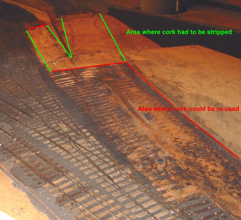 20 20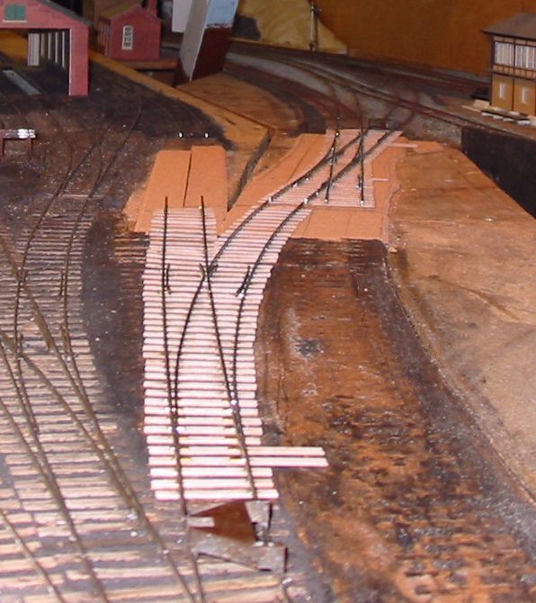 21 21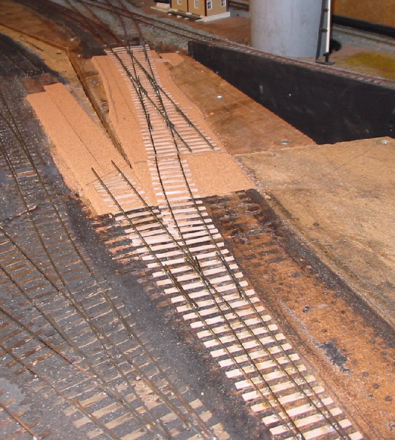 22 22 23 23 |
Laying the track |
|
| Picture
25 shows the track sections, which were built with a bit of
excess rail being trimmed to correct length to suit the board joints.
The track was fixed in place temporarily with double sided tape for
this procedure. The two sections of plain line were also assembled at
this time using C&L bases with a few ply sleepers at the joints. After this stage and before laying the sleepers were stained. This section of track extends over three boards so the laying and ballasting was done in three sections, one board at a time, the single slip first, then the curved point and siding then lastly the connection replacing the old reverse curve. This is seen in pictures 26 to 28. The formation is covered with a thin layer of the white glue diluted about 50:50 with water and brushed out to cover the desired area. The track is then put in place, located with track gauges at each end and weighted down. The ash ballast is spread over everything and gently tamped down. Once a section has dried surplus ballast is swept up with a 2" paint brush and spooned back into its jar. The remainder that eludes this process is vacuumed up so there is no loose ballast getting in the way when spreading glue for the next section. In picture 29 the third section has not yet been swept and vacuumed as it is not fully dry. The remaining task now is to wire up the new sections and replace the point drive linkages. For this task the three boards are taken out and the work done on the bench. |
 25 25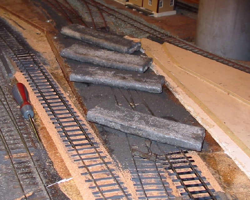 26 26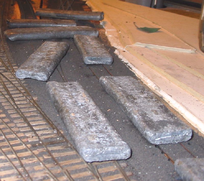 27 27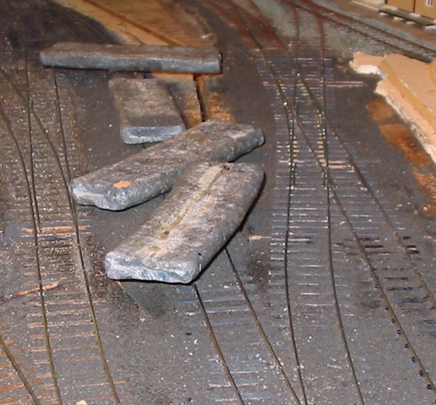 28 28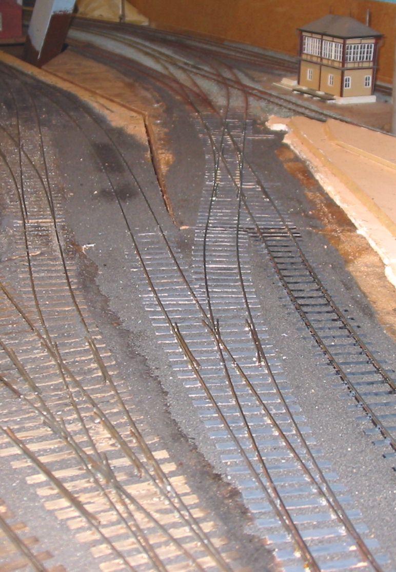 29 29 |