Grovenor Sidings, Railway Modelling
Pages by Keith Norgrove Home Page,
Garratts.
General Electric U20C - Modelling
Project
This page is intended to document my project to model one of
the
U20C engines that were the mainstay of Zambia Railways when I worked on
the line in the 70s and 80s.
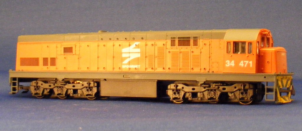
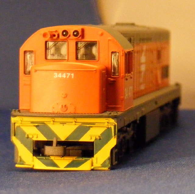
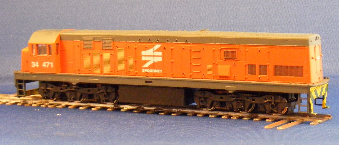
The project is going to show conversion of a Frateschi model
of a South African U20C from 00 to the correct 14mm track gauge, although sold as H0 these locos are actually to 4mm scale.
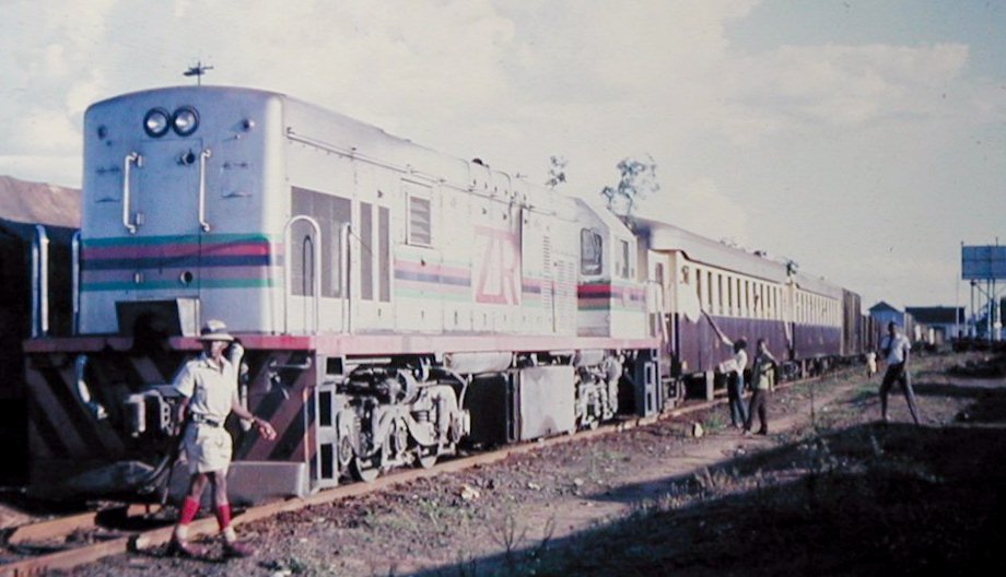
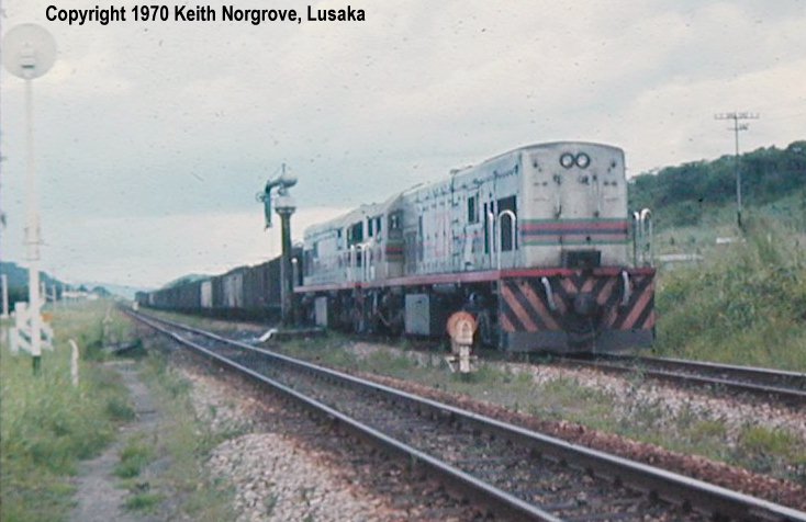
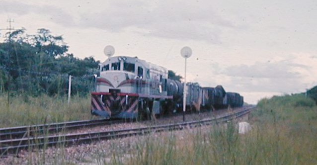
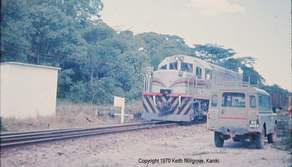
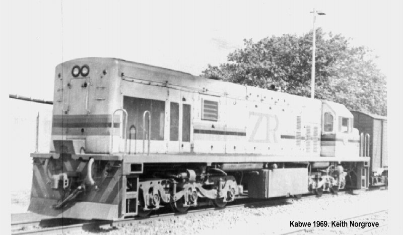
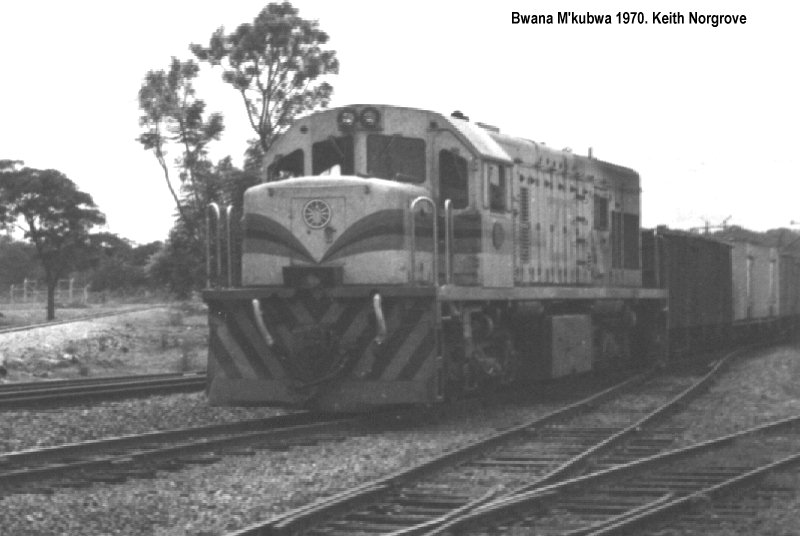
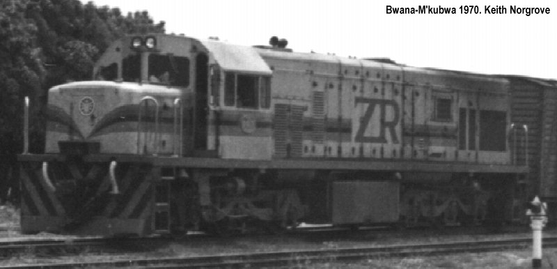
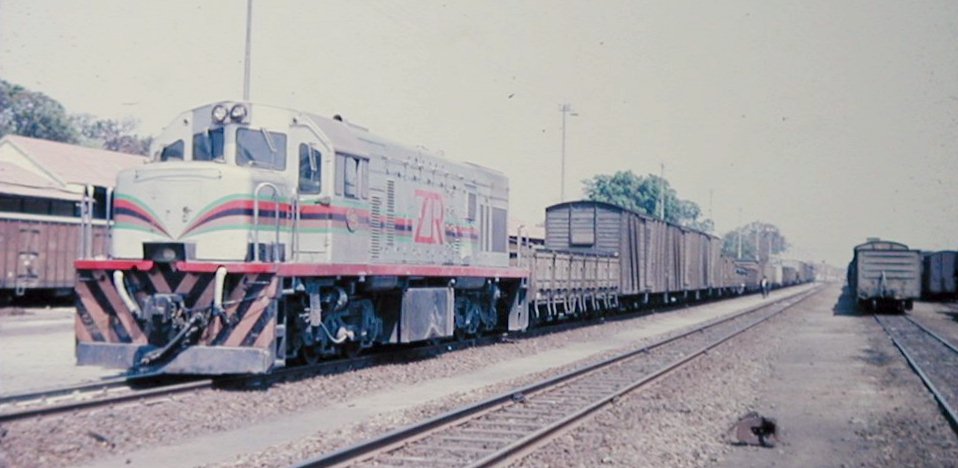
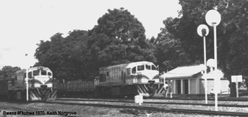
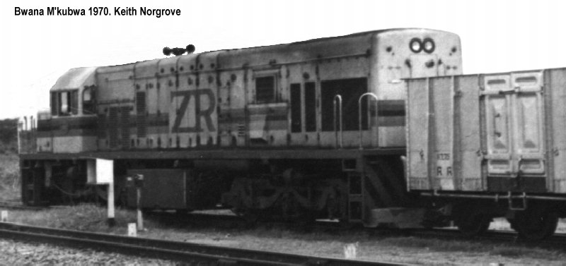
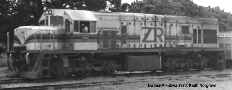
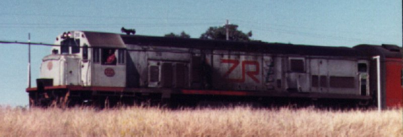
To lay the ground I'll start with some pictures of the real
thing to show the intent.
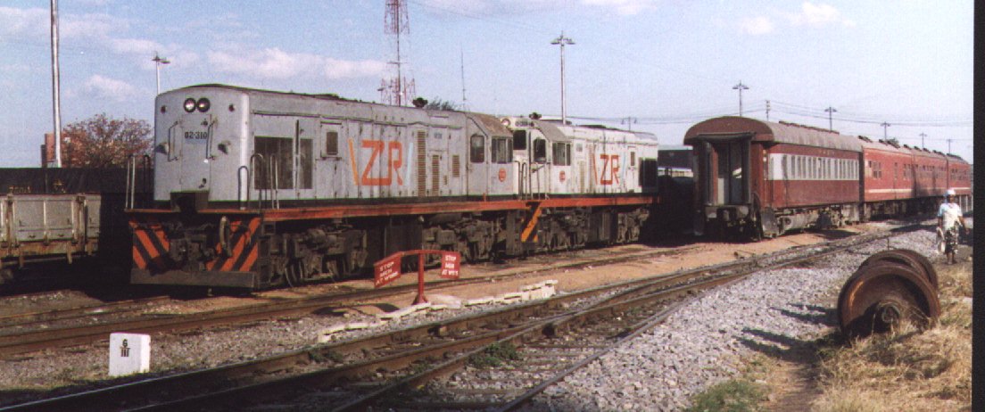
Most of the pics are of the first series, 'long nose U20s', at
the
end are a couple of pics of the second series 'short nose' version I
will be modelling. KN 18/8/08
The official diagrams are here, click on the image to get
a
high resolution version if you want to print them. The U20 diagram is
the long nose version , to get the short nose version you need to take
the relevant bits from the U15 diagram.
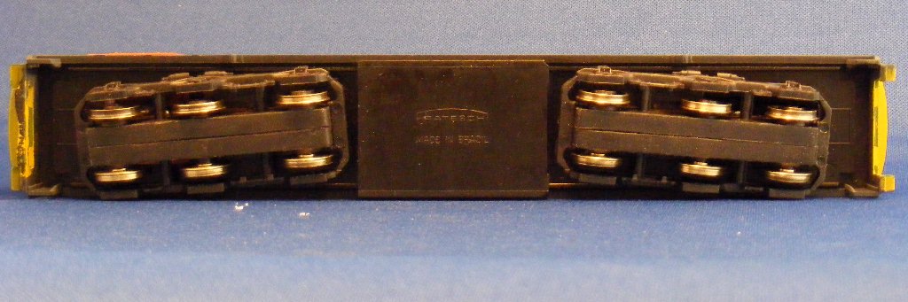
OK Now its time to start in on the model, first a couple of pics more
or less out of the box. Actually I had removed a couple of wheelsets
and turned one pair of wheels to size as will be shown below.
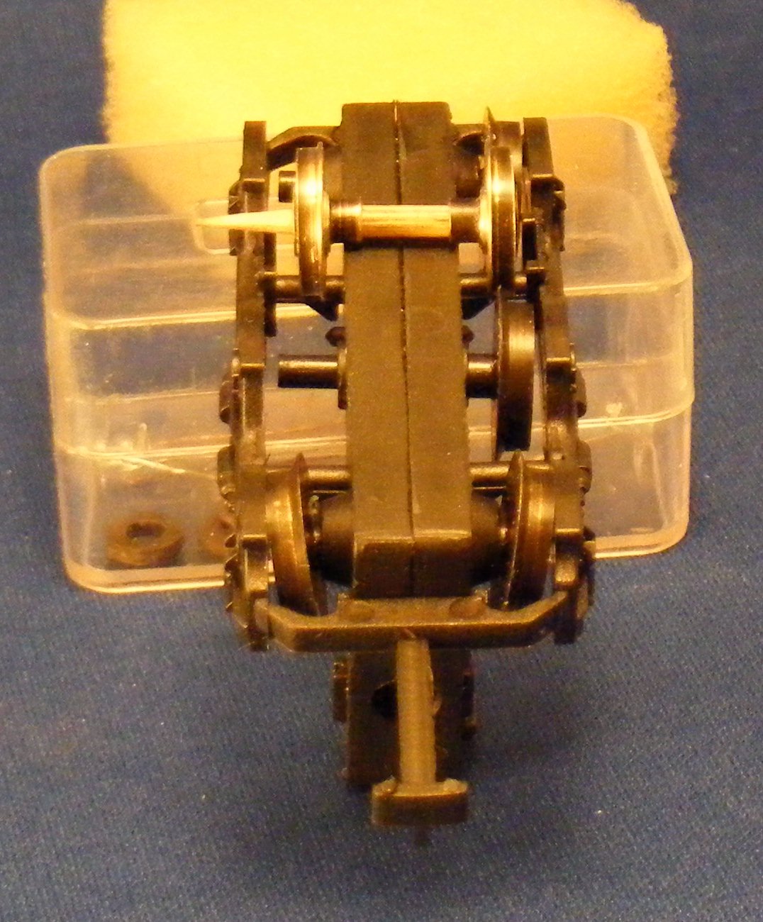
This whole project hinges on the ability to convert the wheelsets to
14mm gauge and finescale so the first task was to dismantle enough to
get a couple of wheels out and onto the lathe. The chassis has a drive
shaft missing as I just replaced the bogie with missing wheels to take
the photos above.
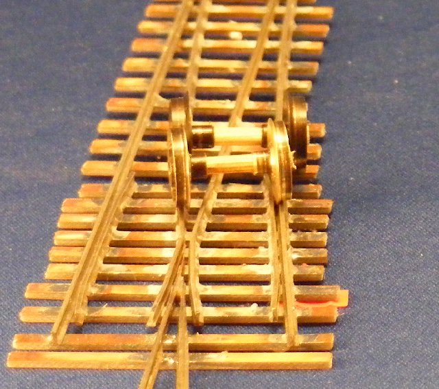
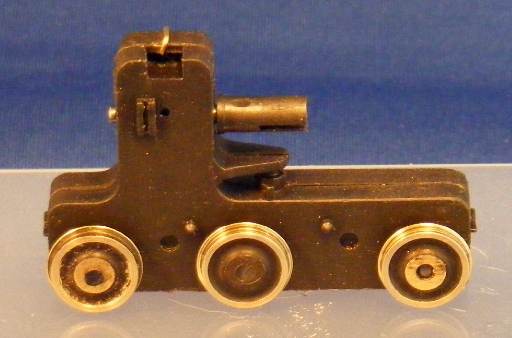
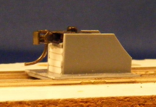
The first pair of turned wheels are pushed onto a temporary wooden axle
for these comparison shots. (I don't want to re-assemble them onto the
plastic geared axles until final assembly to avoid the wheels becoming
loose). The first pic shows the clearance available over the gearbox
for the 14 mm wheelset at 12.7 mm back to back. (The first pair of
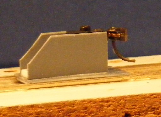
wheels have no axle). The second pic shows the turned
wheelset
and one made up with the unaltered wheels at original back to back,
sitting on a 14mm gauge turnout.
Next task is to get stuck in and turn up the remaining 10 wheels as a
batch. I'll show the sequence used as I go through that process.
KN 21/8/08
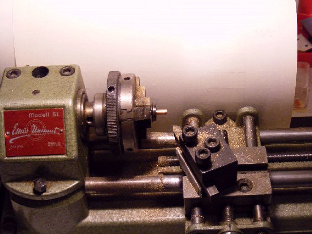
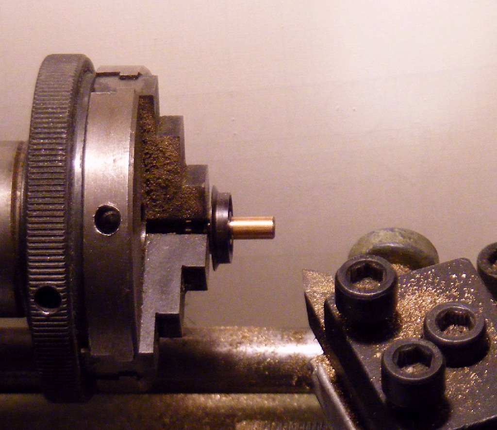
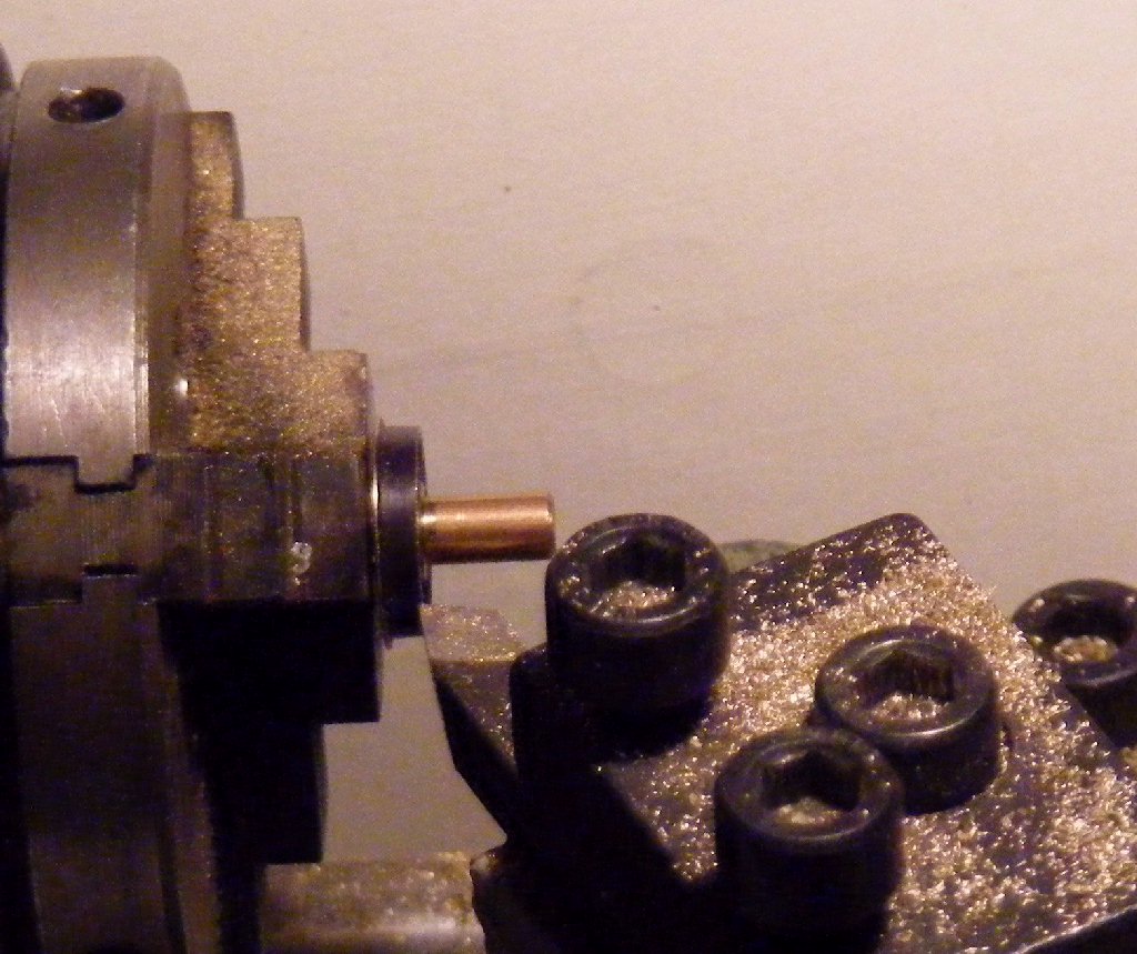
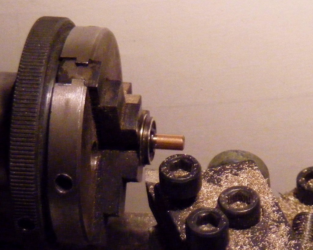
First thing is to set the lathe up.
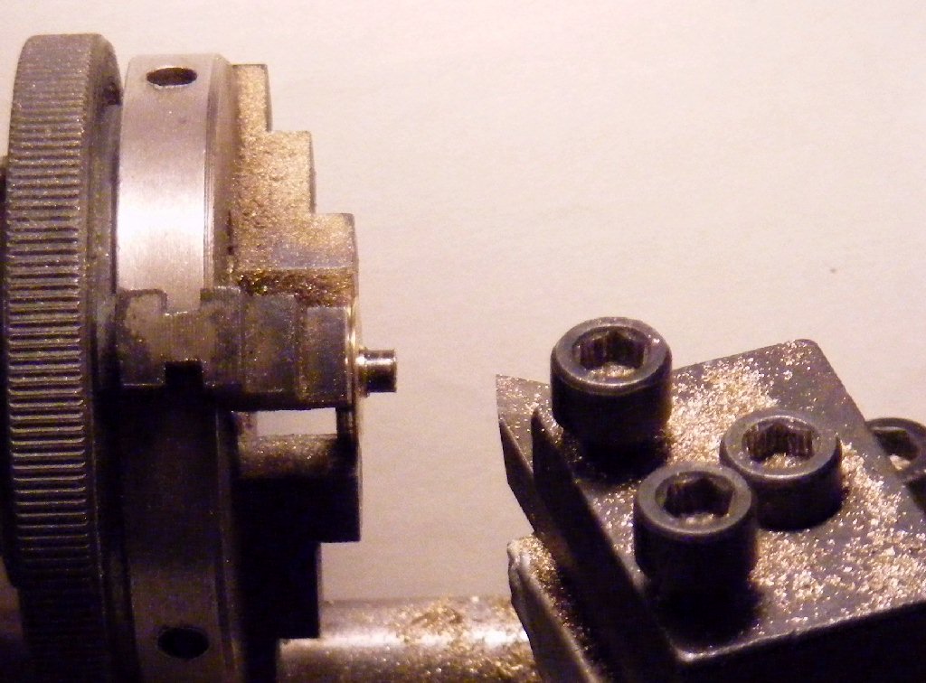
As the wheels have hollow stub axles with rather a thin tube i first
turned up a plug to fit closely within the bore to support the axle
when holding in the chuck, the first wheel is then chucked by the stub
axle for step one, reducing the flange depth. The pictures show before
and after. All steps are repeated for the 10 remaining wheels.
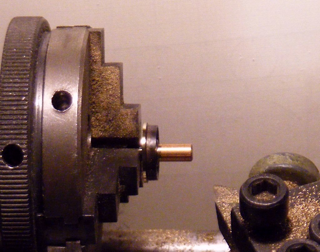
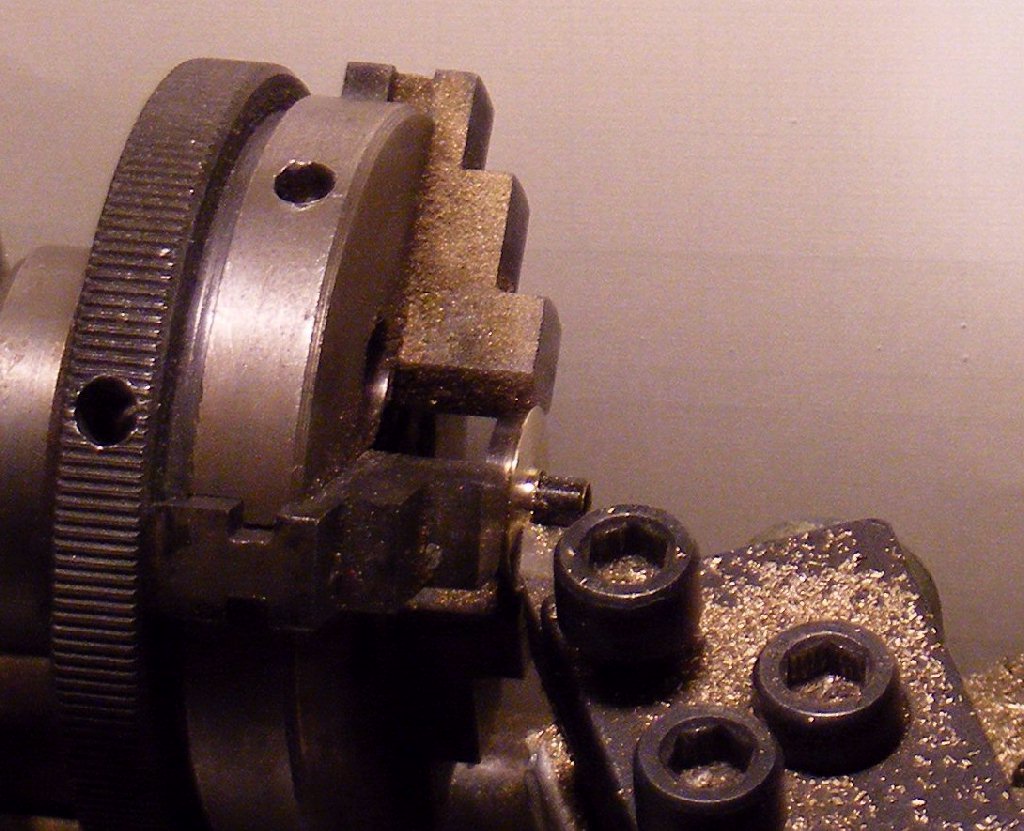
For step 2 the wheel has
to be
reversed in the chuck to reduce the flange width by facing off the back
face of the wheel, again before and after pictures.
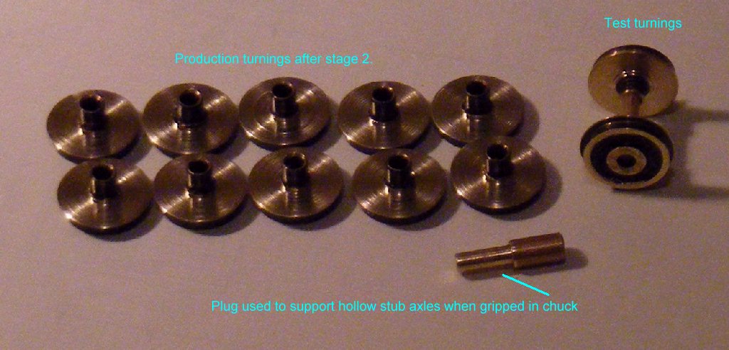
Here step 2 is completed for all 10 wheels, also shown is the plug used
to support the stub axle and the first wheelset completed as a trial
run.
Step 3 is to bring the overall wheel width down to scale by turning
0.5mm off the front face. For this the wheels are held on the stub
axles again.
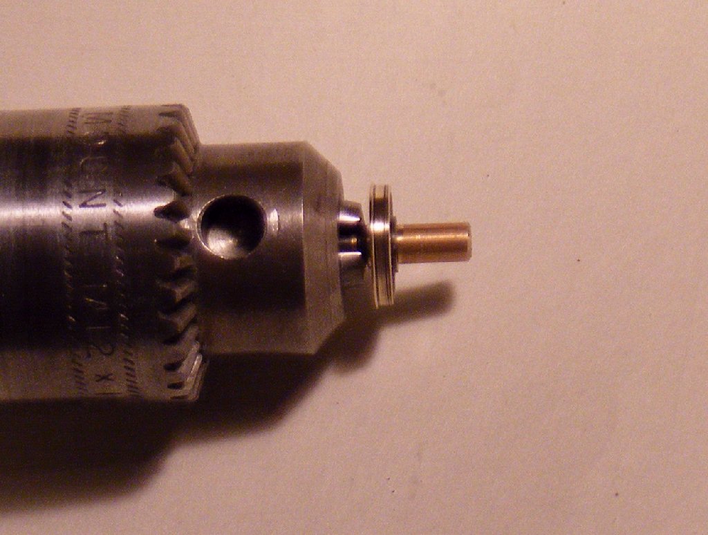
These steps leave a square cornered flange that just needs smoothing
and rounding off a little, to do this I use a needle file gently and
carefully. Its not possible to access the flange with the file with the
wheel in the 3 jaw chuck so it is swopped for the drill chuck to carry
out this action.
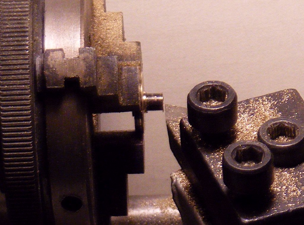
Step 5 is the finish, to shorten the stub axle so that I will get the
correct back to back when the wheels are refitted to the geared axles.
I needed to reduce it to be 3mm from the back of the wheel. Just over
1mm to remove. A file was used to deburr the end after turning.
So, after the second session I have 12 wheels ready to reassemble.
Here are the drawings to show what I was aiming for! Not all that close
really <g>
Next session will tackle the gearbox. KN 23/8/2008
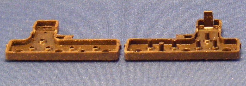
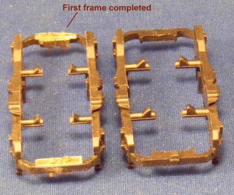
The primary task on the gearbox is to thin down the bearing bosses for
the outer wheelsets so that the overall width is 11mm, or 5.5mm for
each half of the box. This means taking 1mm off each side.
At first I tried filing them down, even with a fairly coarse file this
was hard work, the slippery plastic does not like being filed. When I
got to the second half of the box, which has the internal gear axles
protruding, it was clear that the filing technique risked damaging the
axles. Having second thoughts I fitted a new blade to my scalpel and
tried slicing the plastic off, this turned out to be easy and much
quicker and was used for the remaining 3 half boxes. With that done all
that remained was to re-assemble, removing the bogie mounted couplers
in the process.
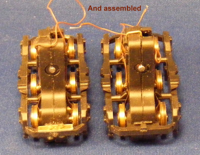
Fitting the pickups was a novel experience, usually when rewheeling 00
locos to P4 its a struggle to bend the pickups out to reach, here the
bend had to be reduced to fit them in the narrower gap behind the
wheels. If experience shows it to be needed it will be simple to add
another wiper for the centre axle.
The bogie was refitted to the frame before repeating all these steps
for the other bogie.
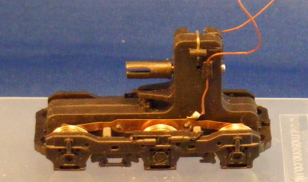
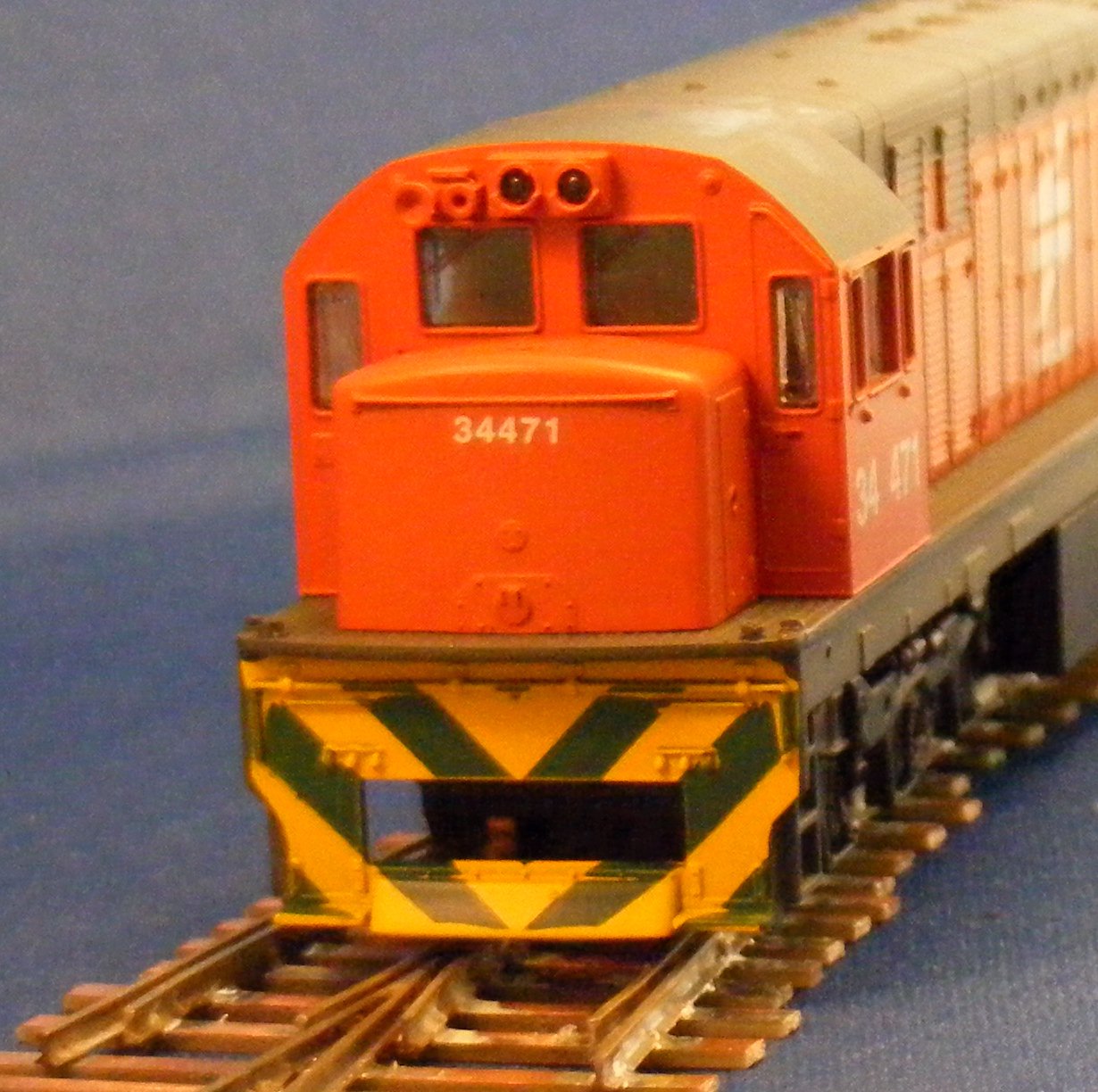
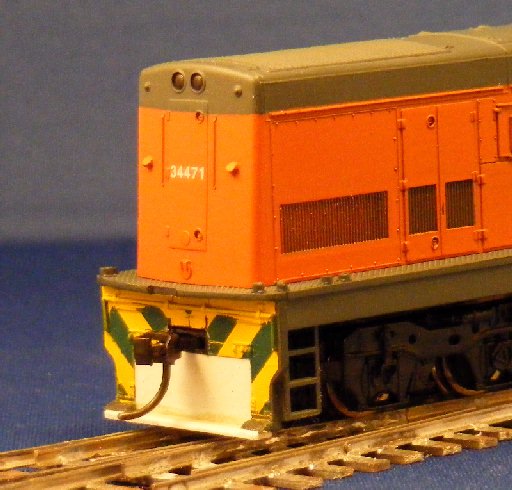
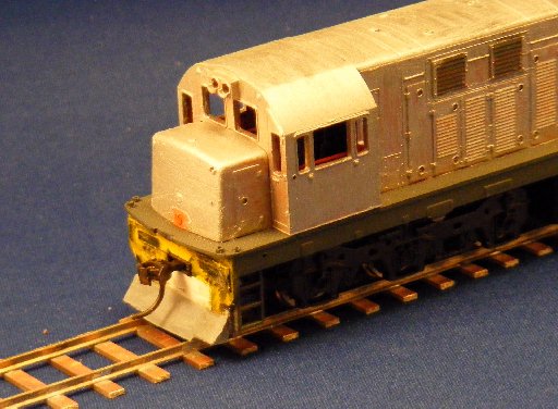
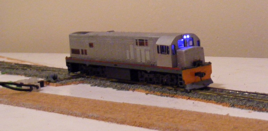
With the body on its ready to start the cosmetic work, apart from
painting the main issues are the couplers and pilots, and relocate the
horns. But at least its now running on the correct track gauge as can
be seen here. At this time I have not made any attempt to reduce the
overall bogie width, the outside frame holds the gearbox together and
any change would have to be carefully thought through. The axlebox
centres as shown in the drawing above are 64" so the width over axlebox
ends should be close to 76", or just over 25mm to scale. The frame
actually measures 27.5 so making the change would be worthwhile and
will go on the 'think about it' list.
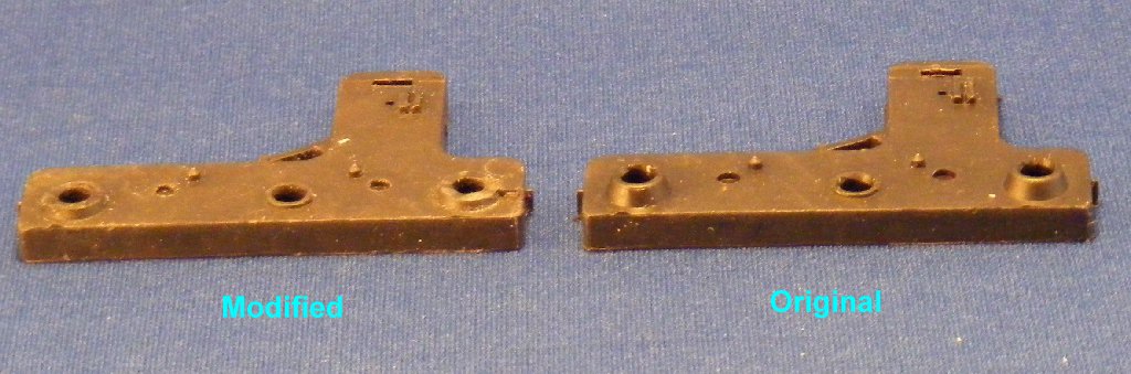
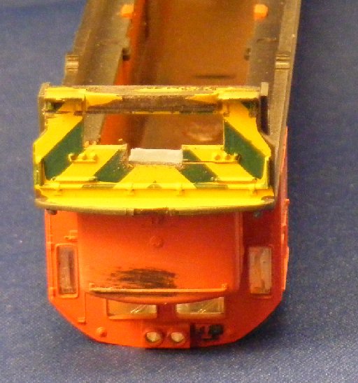
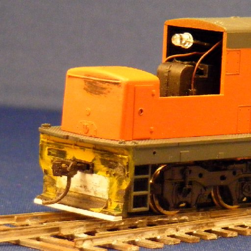
Next item to tackle is the gaping holes in the pilots where the bogie mounted couplers fit through,
also the ZR pilot has a different style at the bottom edge.
First item was to establish the coupler height. Reference to the
drawings shows that the couplers have a centre height 2' 11" above
rail, while the footplate is at 4' 10". After verifying that the
footplate height was correct and checked the depth of a Kadee coupler
box the height for the top of the coupler box was marked on the pilots.
Conveniently this put the bottom of the coupler box in line with the
top of the existing hole, which meant that simple rectangular
plasticard fillers could be used.
Before continueing two preparatory actions were taken, first the
chassis ends were notched to allow space for the body mounted coupler
pads. These notches can be identical at each end.
Next a coupler height gauge for the Kadee couplers was made up, a
simple construction in plasticard with a Kadee 5 fitted, the standard
Kadee gauge cannot be used as it will not fit the gauge and the coupler
height is set to 3.5mm scale not 4mm scale.
Now we can get on with fitting the couplers and filling the pilots.
First I build up a coupler pad from layers of plasticard at the back of
each pilot.
Then with the pad in place the slots for the coupler pockets are cut
and filed to a neat fit on the coupler boxes. I used No.6 couplers for
this as the boxes are short hence did not need an excessive notch in
the chassis ends.
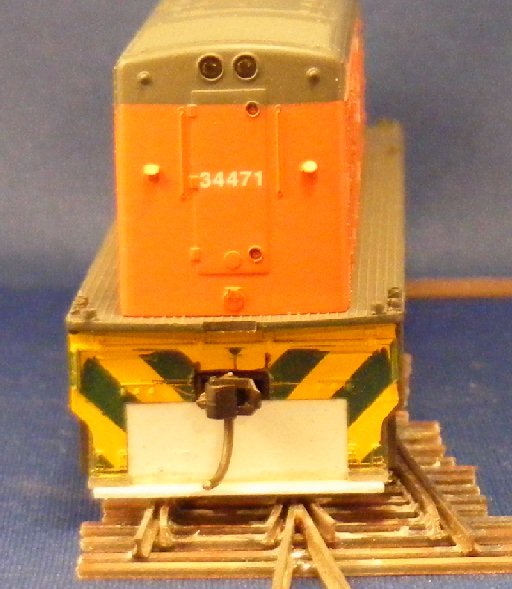
The coupler pads are allowed to dry out then drilled and tapped to fit
the couplers. I use Kadee taps and nylon screws. With the couplers in
place plasticard rectangles are cut tofill the remaining holes in the
pilot and a narrow strip filled horizontally at the base to reduce the
rail clearance and provide a base for the sloping section at the bottom
of the pilot. The existing central section on the front pilot needs to
be filed back ready for future fitting of this sloping section which is
full width on the ZR locos.
NB. during a spare moment at this time I unclipped the cab to check
that the glazing can be removed for painting. No problem, its a
simple clip fit.
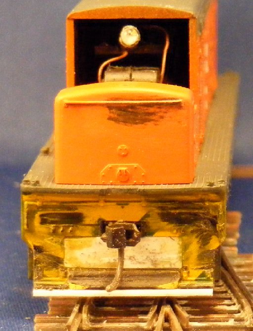
Finally the couplers are checked for height.
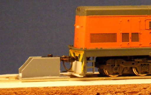
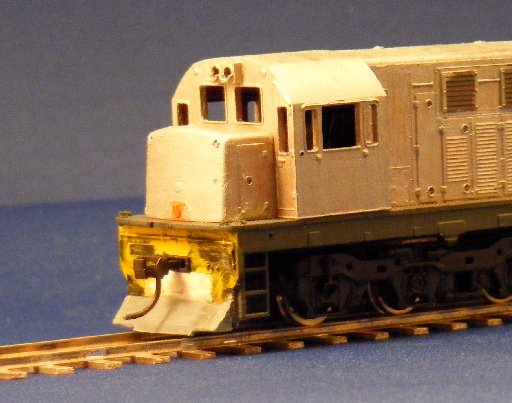
OK after a slight excursion to assemble a bit more track so I have something appropriate to stand it on.
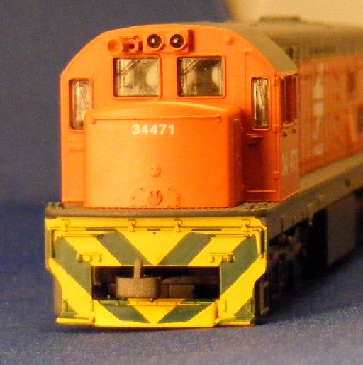
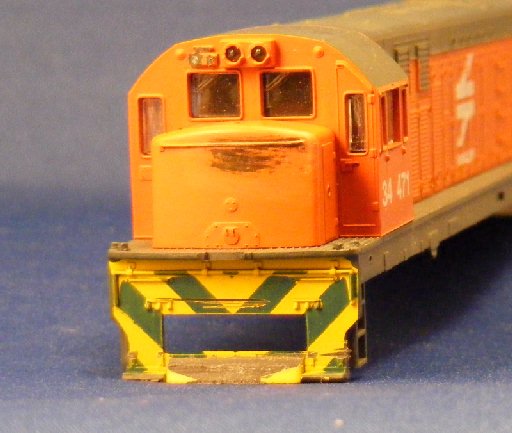
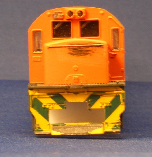
The next step was to complete the lower section of the pilots. Also I
have made a start on hiding that South African orange paint.
Paint doesn't look to good on the nose so will need a rub down before the next coat.
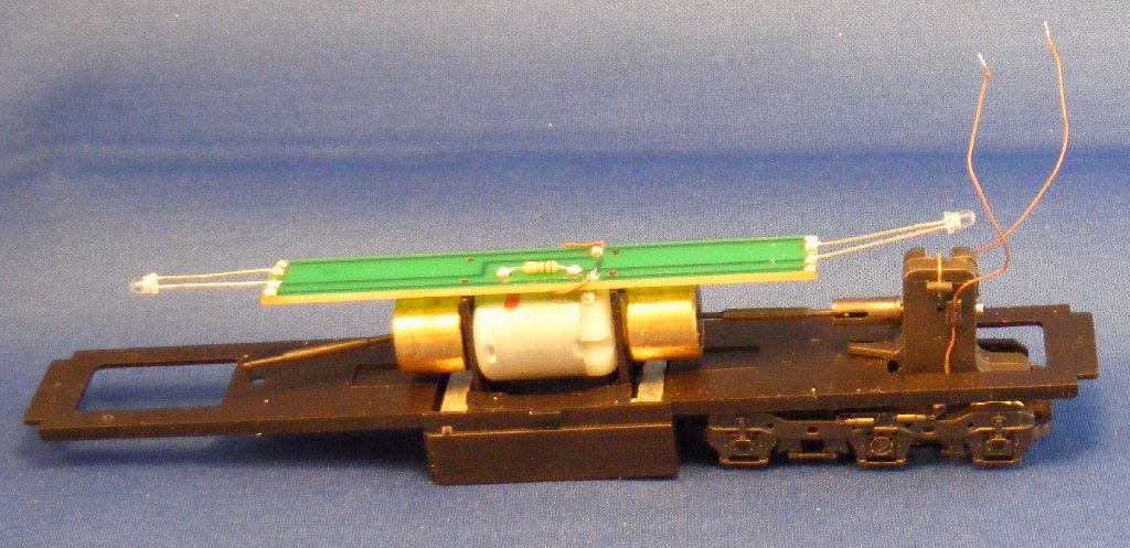
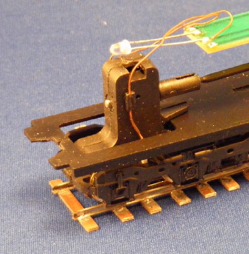
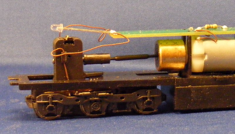
October 26th. Recovered a bit of time and enthusiasm and started on the lights.
The headlights have an LED waving in the air behind them which is a bit
hit and miss as to how much of its output reaches the light pipes, and
at the cab end a lot of this light fills the cab. The tail lights are
just moulded on, so also need to be considered.
My memory of these locos is that headlights were always lit when
running but I don't have any recollection of ever seeing the tail
lights in use although the lenses do show red. So my aim is to improve
the headlights and just represent the tail lights by painting the
lenses red. This will allow use of a decoder with just the stadard
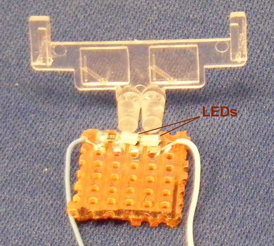
front and rear lamp functions. To get an LED close up behind each light
pipe for the twin sealed beam headlamps I will use a pair of surface
mount LEDs at each end. The spacing required allows these to be
assembled on a small piece of stripboard with a 560 Ohm resistor in
series. The two LED assemblies were built and tested with the decoder
before boxing them in behind the light pipes.
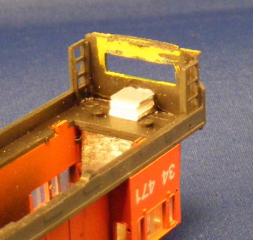
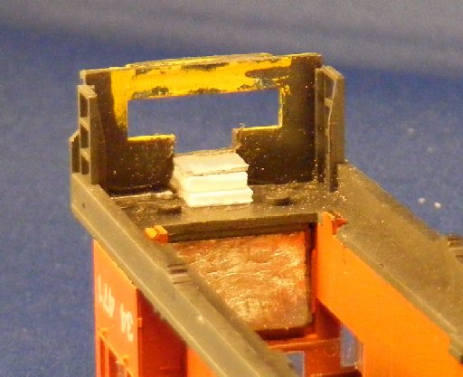
This shows the LEDs series connected with spacing to match the headlight/windscreen moulding.
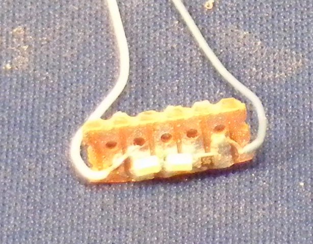
And below the PCB trimmed to size ready to fit. Two of these light boards were assembled.
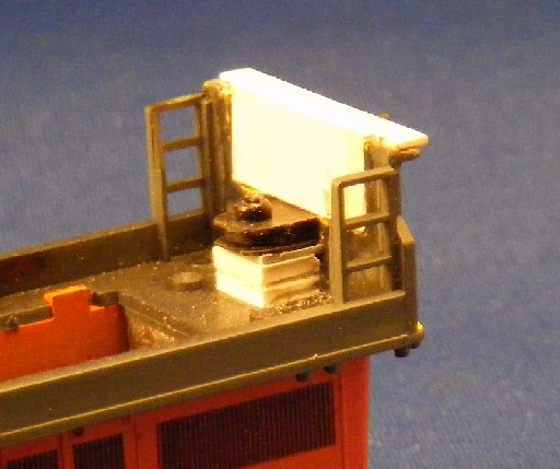
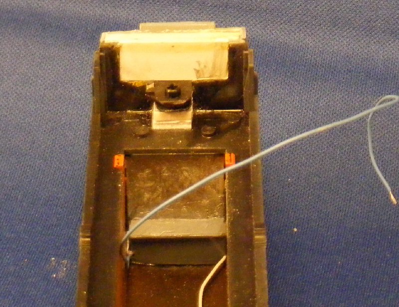
Here the first light unit has been held in place with a bit of bluetack then boxed in with two strips of styrene.
gg
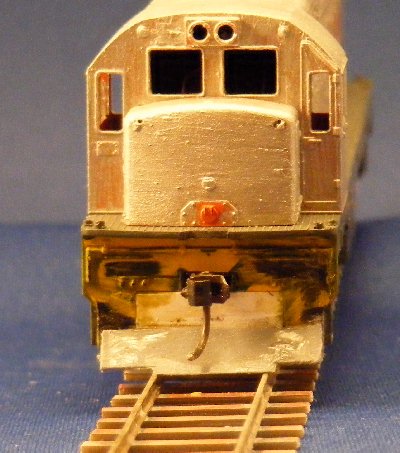
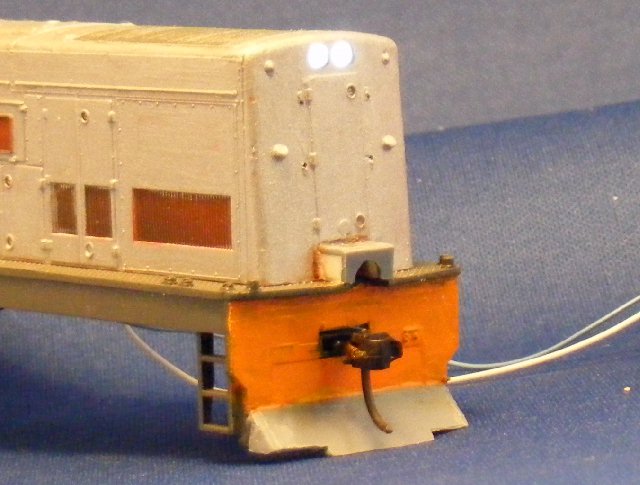
The result when powered up, note the start made fitting the MU cable cover as well.
Boxing in the other LED assembly in the cab roof involved a bit more
work including some black paint on the light pipes to minimise spillage
into the cab, a bit still leaks out but it looks worse in the photos than for real.
Thhe loose cab above then fitted to the body below.
With both sets of lights in place its time to fit the decoder and
assemble everything. However while its in bits I decided to complete
the work on narrow gauging the bogies by reducing the frame width to
the prototype dimension as discussed above.
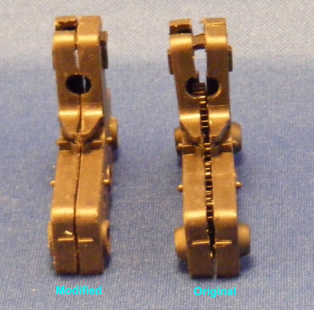
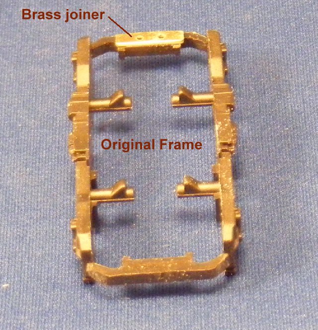
The one piece bogie frames are held in place by two pins each side that
clip into recesses in the gearbox sides, small fillets on top of these
pins hold the current pick ups in place. The frames need to be narrowed
by 2.5mm so each of the 4 pins needs to be shortened by 1.25 mm, the
retaining fillets similarly cut back and 2.5mm removed from each frame
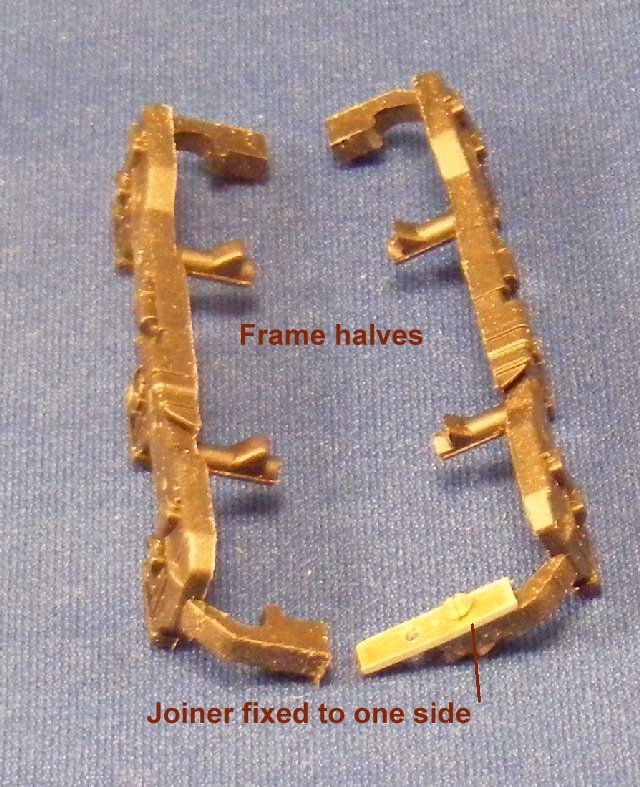
end transom. Luckily there is enough meat in these transoms to rejoin
them with a brass joiner bolted in place with 12BA bolts.
--
--
--
Then it just remains to do the same to the second one and re-assemble
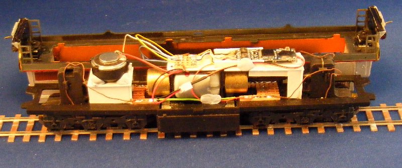
the loco. The following pictures show the various stages in creating
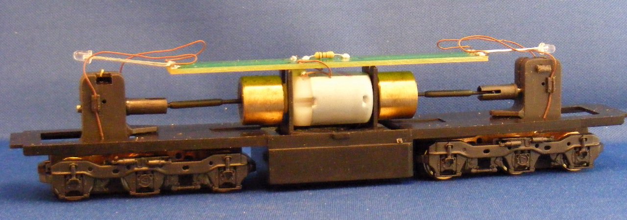
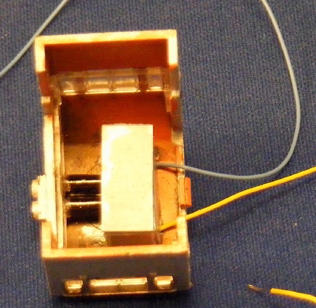
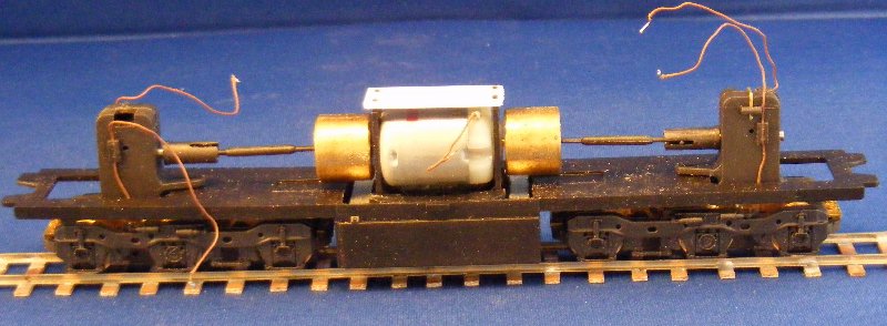
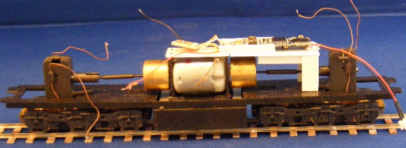
plasticard supports for the decoder.
First a new motor top plate instead of the original circuit board.
Then a support for the speaker.
and a support for the decoder.
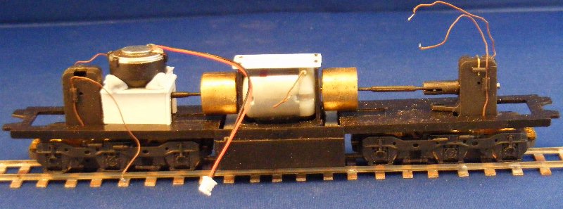
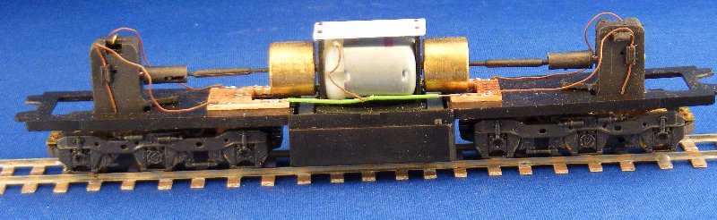
A couple of bits of stripboard to join the pickup wires.
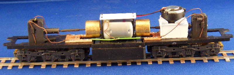
Replace the speaker.
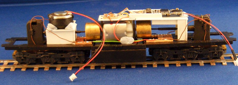
and the decoder.
Then connect all the wires, including those from the lights ready to clip the body back on.
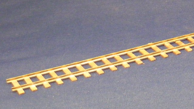
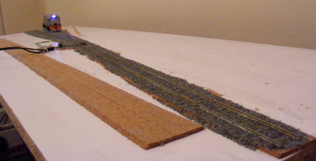
At this point I took time out to lay the track on a test board, replacing the track on a board previously used for a P87 demo.
Just the one turnout and three lengths of track to allow for shunting up and down.
NB. A prototypical train for one of these locos would be 6 metres long
to scale and fit comfortably in the 9 metre loops designed to fit the
load for a 20th class Garratt
The track was laid by my usual technique, glueing track and ballast in one operation.
See 'Shed relay' here for details.