| Model Railway Constructor | July 1967 |
PROTOFOUR --- 7 a new scale modelling standard by a model standards study group J.Brook Smith, M.S.Cross, D.E.Jones |
The Protofour series has now reached the stage where the layout may be developed. We have plain track, but every model railway layout needs turnouts to transfer traffic from one road to another, and once a turnout is set into our plain line, it creates immediate interest. Unfortunately, it also creates technical problems, and the quality and efficiency of the turnouts either makes or breaks the layout - far too frequently the latter. These tragedies are usually the result of a lack of understanding of the workings of turnouts or a disregard of their limitations. To analyse the workings and limitations of turnouts we will adopt the usual Protofour procedure and examine the prototype before discussing the model.
General
Although most British turnouts are built to standard patterns, there is no such thing in the prototype as the cardboard-boxed "Left or Right Point". Prototype turnouts are produced by assembling separately made switches and crossings into a single unit suitable for the site in question. The desired traffic speeds and the limitations of the site will determine the radius of the branch road, and this radius will in turn determine the length of the turnout and the angle of the crossing. However, if each and every turnout were to be tailored individually to the desired radius, manufacture and maintenance would prove extremely expensive. Railway companies therefore stock a range of standard switches and crossing units, which are used for all normal operations.
Standard Units
The SWITCHES are used to direct traffic to the main or the branch road, and are made as a pair.
The CROSSING (common or acute) allows the wheels of the stock to cross the opposite running rail.
By joining these units with closure rails a turnout is formed, and together with the OBTUSE CROSSING, which complements the common crossing in a "diamond", these switch and crossing units are used to make every turnout and junction formation used on the railways.
In view of their universal application, the range of standard switches and crossings is surprisingly small. The switches are made in 6 patterns from "A" to "F" the crossings are referred to by the ratio of the angle, e.g. 1:8 or 1:9¼.
Standard Leads
When the main road of the turnout is straight, the Permanent Way engineer consults tables giving the standard "lead" - the distance from the toe of the switch to the nose of the crossing - for each combination of switch and crossing, and each lead will correspond to a certain radius of the curved road. Thus he may order, for example, a "standard Bullhead B8 Left Hand turnout". The type "B" switch pair and the 1:8 crossing will then be assembled in the Permanent-way yard, and together with the requisite closure rails, timbers, check rails, and switch fittings, will be transported to the site for assembly into the finished turnout.
It is clear that where not one, but both roads of the turnout are curved either in the same or in opposite directions ("similar" or "contrary" flexure), the lead or the angle of crossing will vary. In these cases the crossing angle must be calculated by trigonometry or established by scale drawing.
Natural Turnouts
Our example, the "B8" turnout, is a "natural" turnout in which the radius of the switches, the radius of the closure rails, the lead, and the angle of crossing, all combine to produce an even radius through the curved road of the turnout. However, many turnouts are not "natural" and it will be realised that the various switches and crossings can be combined in many different ways to give different patterns of turnout to suit the various sites on which they will be assembled.
It is this remarkable flexibility of use that makes prototype turnouts such fascinating objects to study, and the unlimited possibilities of switch and crossing combinations in model form should be one of the most rewarding aspects of the hobby. Unfortunately, as with so much other basic equipment, correctly designed switches and crossings are simply not available, and this accounts for the almost total absence of really authentic scale model railway track. At the time of writing, every item of scale trackwork has to be made by the modeller himself, or produced by specialist firms, and very few suitable components, and even less sound advice, exist to assist him in this venture.
Detail variations
Although prototype switches and crossings are of a standard general design, the smaller details vary considerably. Switches may be planed in different ways to give "straight", "semi-curved" and "curved" blades, while the toe of the switches may be straight-cut" and nestling in a slight joggle" in the stock rail, or "undercut" and fitted in the rear of a "set" in the stock rail. The crossing is built from rail, the main running rail being planed to form the nose of the crossing, and termed the "point" rail, while the secondary running rail is spliced into it behind the planing. The point and splice rails are bolted together to form the "vee" of the crossing; the nose is held down by a bolt or by means of special blocks, and the whole unit is held in a special chair. The wing rails are bolted in turn to the vee, and spacing blocks ensure that the flangeway is maintained at the correct spacing of 1¾in.
The chairs for the crossings and switches are also to special design, and are slide, block, or plain, and where necessary are given codes for identification. Thus the chair under the crossing nose is the "A" chair, and the "B", "C", and "D" chairs are set at 2ft 6in spacing away from the switches, and the "X" and "Y" chairs towards. Switch chairs and timbers are not all regularly spaced, and average approximately 2ft 4in centres.
1 Protofour B7 turnout, right hand. A 1:7 crossing with type B switches drawn full size for 4mm scale.
Timbering
Although the spacing of the timbers is standard, the methods of setting out vary. Some companies, notably the Great Western, aligned their timbers at the crossing with the centre-line of the vee, and others, such as the LPTB, set the timbers according to the main road. The latter system is nowadays more general. Diamond crossings and double slips, however, still have the timbers symmetrically arranged and at right angles to the centreline joining the two common crossings.
Where turnouts and diamonds are combined to form junction layouts, timbering is individually arranged, and much variety may be noted at these locations. What is still common to all is the setting of the "A" chair, and therefore the crossing timber, under the nose of the crossing, and very long timbers, or timbers set closely end-to-end, are avoided because of the difficulty of packing the ballast.
Timbering for turnouts is heavier than ordinary sleepering, being 12in by 6in, as opposed to 10in by 5in in the latter. Timbers are provided in standard lengths from 8ft 6in, in 6in stages to 15ft 0in. Longer timbers may be provided, but these become increasingly expensive, fragile, difficult to transport and awkward to handle with increasing length. Often two smaller timbers may be half-jointed and bolted together on site to provide the necessary length. Nowadays crossing timbers are invariably provided for the closure rails, but in pre-grouping days some companies simply interlaced plain tracks between the switches and crossing. These turnouts are probably very rare now, if they can be found at all.
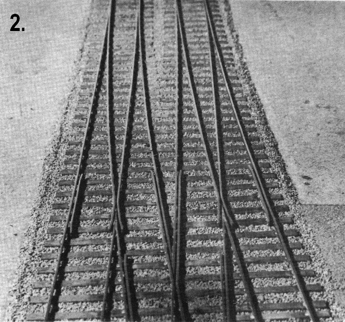
2 Crossings on a Protofour layout under construction, with B8 turnouts and non-standard lead.
Modelling considerations
It is plain from the foregoing that we must revise our approach to "points" and instead we must consider switches and crossings as separate units. The main features of prototype switches and crossings applicable to modelling are as follows:-
(1) They are separate units which are combined with closure rails to fulfil the requirements of a particular turnout.
(2) They are specially made to high standards of accuracy, and rarely if ever manufactured on site.
(3) They are made in a standard range of patterns, and are not produced to individual specification unless absolutely necessary.
(4) They have standard timber spacings and are fitted with specially designed standard chairs to ensure uniformity of construction.
(5) They are usually combined with closure rails to standard "leads" which predetermine the radius of the branch road of the turnout.
Critical Factors
Crossings in particular are the most critical items of trackwork on any layout, be it prototype or model. In the full sized article they are made under carefully controlled conditions, and the flangeway dimension is rigidly held at the standard l:in setting by means of heavy bolts passing through cast iron spacers. Delivery of prefabricated units to the site of the turnout removes the hair-raising prospect of unauthorised tinkering with the flangeway dimension and the disastrous consequences that would follow. Modellers often fail to realise that the settings of their turnouts are equally critical, (and in the case of BRMSB "00" gauge, more so,) as we have seen in part 2 of the series. The situation often becomes further complicated when the critical flangeway is situated on the minimum radius of curve for the layout's rolling stock.
The five rules for reliable running given in parts 1 and 2 of the series, and the general principles of determining the minimum radius of curve given in part 3, must be applied to scale model railway turnouts.
Scale Proportions
The smallest standard lead for which components were stocked by the LMS and the LNER was the A4, and it is interesting to compare the radii of some typical prototype units and their equivalents in the model scale. It is always maintained that scale turnouts take up too much room, and must be modified for the model. The A4 has a scale lead of 6¾ in and a radius of 20½ in, but it is certain that it would have involved restrictions on the types of locomotives used. The GWR would not countenance less than the B6, and British Rail also use this minimum for their Flat-bottomed rail turnouts. Even the B6 has only 9in lead and 4ft 0in radius, and yet it will accept anything run on the prototype tracks. The "A" switch will give a shorter lead for the same value of crossing than the "B" switch, and for modellers the A6 or the A5½ probably represents the smallest turnout that can be reproduced exactly to scale without restriction of the stock. The lead of the A5½ is nearly 8in and the radius nearly 3ft 6in. For comparison the largest turnout with standard lead is the F20, with 26in lead and 50ft radius (!)
Conclusions
From this discussion it is clear that scale model turnouts have to be treated with the respect which they deserve. The critical aspects of the flangeway and the minimum radius of curve must be fully considered before the turnout is constructed. In short, the layout must be designed around the turnouts, and not, as is often the case, the turnouts forced into layout situations where they cannot possibly work effectively. If the railway service, with its complement of trained engineers, finds it necessary to take special precautions in the construction of switches and crossings, it behoves us, as amateur modellers, to make our equivalent constructions under the controlled conditions of jig-building. Through the understanding of the critical factors of turnouts, we can produce, in the jig, turnouts guaranteed to work faultlessly the moment they are laid, and precisely how this happy state of affairs is achieved, we will discover in the next article in the series.
Modellers wishing to obtain further inforniation about prototype turnouts are advised to refer to "British Railway Track" published by the Permanent Way Institution, and to the article "British Permanent Way" by W. P. Alexander AMICE, in the Oct-Dec. 1960 issues of the Constructor.
|
|
|
|
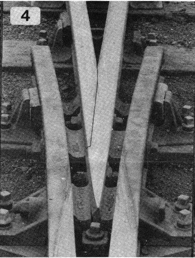
| 3 A trap point laid with pre-grouping rail. This switch is type "A" with five slide chairs, each of which is bolted to the stock rail. | 4 Close-up of a typical crossing. Note the special chair under the crossing nose, the holding-down bolt at the point rail, the spacing blocks, the bolts through wing rails, blocks and vee. the point and splice rails (marked for easier reference) and the special "C" chair, with inside key. One side appears to have been struck by a BRMSB flange! | 5 The switch blades of an interlaced turnout. Six slide chairs identify these switches as Type "B" and they are undercut, with a set in the stock rail. The undercut and set have been marked for clarity. | |
|
|
|
|
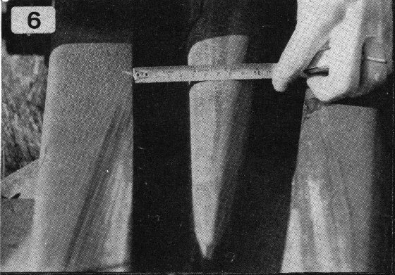
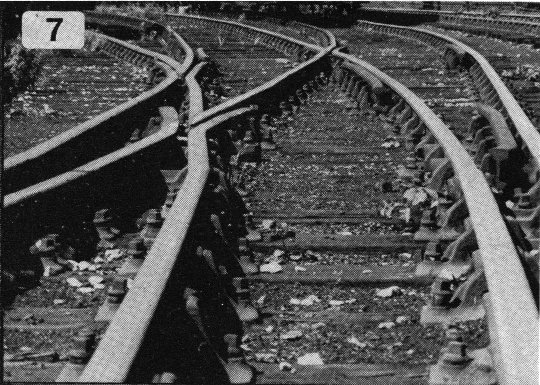
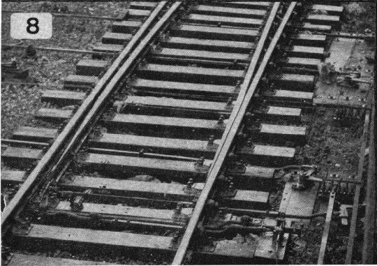
| 6 The most critical dimension in modelling, This Bluebell Railway flangeway measures exactly 1¾". Note the detail difference in the planing of the crossing nose compared with the L.M.S. type in Photo No. 4. | 7 Track is not always the transitioned construction that we imagine. However, the crossings remain accurately aligned and flangeways correctly spaced. | 8 Type "D" switches at Marylebone. Note the interlocking bar on the right, and associated rodding. | |
|
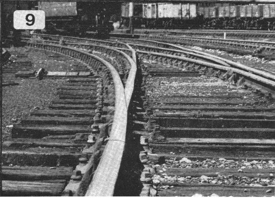
9 The switches of the turnout in Photo No. 7. The set, and the method of planing the switch rails, is clearly seen. | ||
Copyright - Model Railway Study Group, reproduced with permission.
Back to Magazine Index, Back to Site Index.