Updated: 27 August 2003
Intro-Chassis WorkRewheeling
|
A workhorse Class 37 has been on my to-do list for a long time and I have gradually accumulated a collection of parts towards this end. One of the first was a secondhand Triang model of which only the body looked to be of any use and has survived. More recently a Lima 37 joined the collection and with the advent of Ultrascale "drop-in" wheelsets these were tried. OK I suppose if you only have a flat layout and don't want good slow running, the wheelsets were fine but not the motor and chassis. On my grades it was slipping with 2 coaches. I also have an Overland chassis intended for an SD40 or some such which has fully sprung bogies and I have spent some time pondering on how to convert these to P4, I have got as far as obtaining some etched frames from Bill Bedford but have not yet cracked the wheelset conversion.
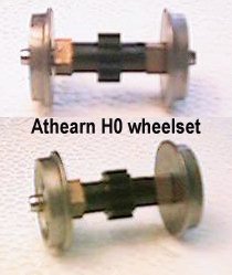
During this process I came across an Athearn PA at a good price in a swapmeet and brought it home to see what it could do. Performance on H0 track was excellent so I started scheming a P4 conversion. The bogie wheelbase at 52.5mm is a touch short of the 54mm needed for the 37 so I spent some time looking at the effect behind the Lima frames and eventually decided I could live with the discrepancy.
So what follows is my conversion effort.
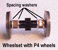
The stub axles are 2.4mm diameter and project through the wheels into the outside dummy frame, this makes them long enough for P4 use but the axle and tyre do need to be electrically connected. At this point I was stuck until I had a brainwave and checked out some of my original Mark 1 P4 coach wheels, the turned steel type with central insulating bush. By some miracle they were a comfortable push fit on the Athearn half axles and were nicely fixed with solder paste.
For those of you without stocks of old Studiolith wheels, an excellent alternative is now available and has been successfully used. Branchlines supply uninsulated nickel silver wheels which can be fitted on 2mm stub axles, use of an Exactoscale 2.4mm od sleeve will allow the assembly to fit the Athearn bearings and gear.
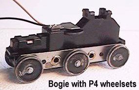
This led to the crucial test, the wheelsets were assembled with 8BA spacing washers to take up the space on the axles, fitted to the bogie and the bogies reassembled. Somewhat to my surprise the rewheeled PA (a cabless B unit so it looked a bit odd) operated in an exemplary manner, hauled the required 7 coaches up the hills and stayed on the track. Surprise as it is not sprung, and not really equalised, however, the centre axles can lift slightly which means they are not normally carrying any weight and all axles can drop a bit.
Anyway this proved that conversion was practical and I could move on to the next stage.
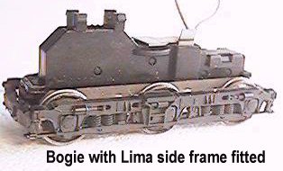
The only item left to complete the bogies was to fit the Lima side
frames. First the
coupler mounts were cut off the Athearn bogie keeper plate and the
situation examined. The
Athearn dummy frames are in seperate side pieces and plug in to holes
in the bogie frame assembly eyelets. They are held in
just by friction. It appeared very difficult to replicate this with the
Lima frames but
the eyelet holes seemed the only practical fixing point. The centre was
cut out of a Lima frame leaving the sides connected by the end beams.
The frames are then flexible and could be sprung into place if a
suitable pin could be
devised.
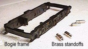
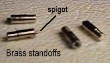
After a couple of false starts the solution was found to be to make
4 standoffs from brass rod. The first 2mm was turned to fit
nicely in the eyelet holes and the rod cut off to give a 5mm standoff.
A hole was then
drilled in the plain end to take 0.9mm brass wire, a piece soldered in
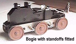
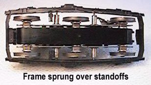
and cut off leaving a 1mm spigot. With the 4 standoffs in place the
Lima frame was sprung into place over the spigots and carefully adjusted to
the correct position. The brass standoffs were then carefully heated with the iron and the
frames squeezed so the spigots melted into the back of the frame.
Fitting the second bogie frame was left until after the body and couplers were finished as having a bogie available with only inside frames helps with establishing clearances.
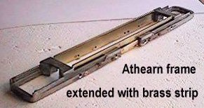
To achieve the correct bogie centres the Athearn underframe needs lengthening by 28mm.
After some examination I concluded that this was best accomplished by cutting the frame
into 3 pieces, first the motor mount was cut off with two horizontal and two vertical cuts
leaving the mainframe with straight sides. After trying the hacksaw and finding it
hardgoing ( a new blade might have helped) I tried the cut off wheel in the Dremel and
found this easier. The frame was cleaned up and then cut in two through the middle. Two
brass strips 1/2" by 1/16" were cut to length and clamped accurately in place,
frame and brass drilled through 8BA tapping size, then seperated so the brass could be
tapped and the frame drilled out to clearance and countersunk. They were fixed with a
total of 12 *8BA bolts. (Note the extra holes in the pictures
as my original idea came out misaligned, hence the clamping method)
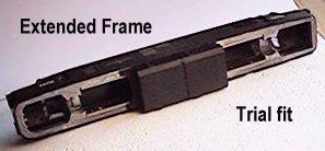
Remarkably the overall length was spot on but the frame would not fit into the body as the ends were not the correct shape. The front end of the frame just needed the taper extending a little, the rear end needed a complete taper and a curve putting in the end. This was accomplished with a large file, working at it until a snug fit in the body.
Now the frame looked great, but there was no place to put the motor, the motor has to
sit down between the frames and is fixed with a couple of plastic clips into 4 holes in
the (removed) mounting block. The Lima fuel tanks are large enough to hold the Athearn
motor mount and some additional lead weight but has to be fitted in place somehow. Looking
at the frame it appeared that the gap between the Athearn frames could be used to form a
clip to hold the tank in place. To do this an additional piece of brass 1/4" by
1/16" by 28mm was soldered onto the bottom edge of the main frame brass strip in the
gap.
The tanks were then cut from the Lima frame leaving a piece of sidemember fitting the gap
in the Athearn frame. With the tank held up into place a couple of 60thou plasticard
pieces glued inside the Lima frame made a clip holding on the brass piece.
The Athearn motor mount had to be trimmed about a millimeter on each side to fit in the
tank, achieved with the dremel cut off disk and the large file again, some fillets also
had to be removed from inside the tank. By fitting the motor mount tight up to one end of
the tank it is neccessary to extend the Athearn drive shaft at only one end and more room
is left for the DCC decoder. The remaining space in the tank was filled with lead sheet to
counterbalance the off centre motor. The plastic motor mounting clips have to be thinned
down to fit between the brass strips, difficult stuff to file but persistance does it.
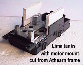
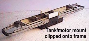
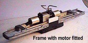
Pictures show the tank with motor mount, the tank clipped to the frame and the tank and frame with motor fitted.
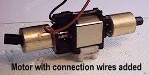
The original Athearn design has one side of the motor connected to the frame and the other to a contact strip above the motor, the frame and the contact strip are connected through rubbing contacts to the opposite sideframes of each bogie. As I am using DCC I needed to isolate the motor, at the same time I wanted to enhance reliability by wiring direct to the bogie frames, eliminating the rubbing contacts. The bogie design is such that the main frame remains connected to one side rail.
To isolate the motor the top contact strip was discarded and then the top and bottom
brush retaining clips exchanged. Wires were then soldered to
these retaining clips before re-installation. (The exchange is required as the bottom
clip has springs punched out of it to contact the chassis, the exchange puts these on top
where they do no harm). To allow removal of the bogies a 2 pin plug and socket is needed
for each, also for the DCC decoder a 4 pin socket is needed. A small piece of pcb
veroboard with 4 tracks was used to make the connections, this is soldered to the motor
brush wires and the three sockets attached. When
dismantling it stays with the motor.
The DCC decoder has provision for lighting controls which I have not yet used in this installation.
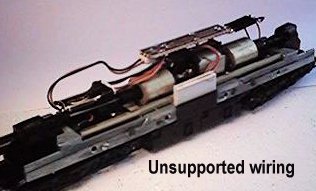
Simple plasticard frames were built to create a shelf over the flywheels and driveshafts for the electrical components.
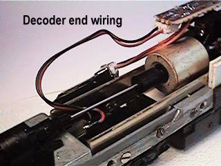
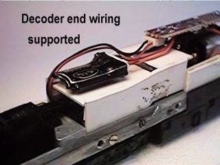
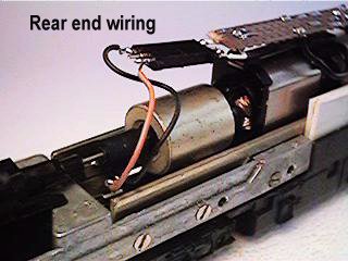
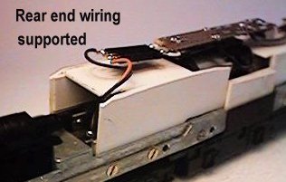
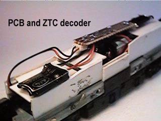
Picture show: Decoder end loose wiring and support in place, rear end loose wiring and support in place, complete assembly.
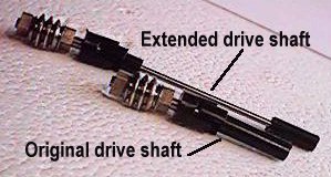
The extra 28mm of length between bogie centres meant that the drive shaft at one end no
longer reached the gearbox. It proved possible to drill a 1.5mm hole down the centre of
the splined shaft and then cut it in two using a piece of 1.5mm rod to increase the length. This was sufficient to operate
satisfactorily but the motor is a bit further from the other end than it was originally
and I feel that the splined shaft at that end does not fit far enough into its socket for
long term reliability so will be extending that shaft in a similar way.
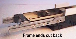
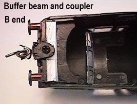
Looking at the space available at the chassis ends it was apparent that fitting the
buffer beams and couplers to the chassis would be very difficult. I therefore decided to trim the ends of the chassis and fix the buffer beams and
couplers to the body. The Lima buffer beams were therefore cut off the ends of the
original chassis and glued into the end of the body, taking care to get the height
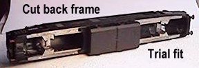
correct. The chassis could now again be tested for fit.
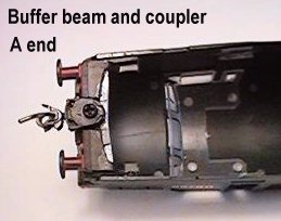
(Buffer beam and coupler fitting shown in these two pictures, A-end
and B-end).
Now that the buffers were attached the bogies could be inserted and the ride height checked, this was now found to be 0.5mm high. And here you can learn from my mistake, do not fix the tank retaining clips before this stage or, like me, you will have to persuade the glue to come unstuck! The ride height is controlled by the top edges of the frame contacting the bottom of the driver's door recesses inside the body shell. A bit of work with scalpel and scrapers was required to remove the half millimetre from the bottom of each. Once the height came out correct, the tank and motor mount could be refitted, a 20thou plasticard spacer was needed between the top of the tank unit and the bottom of the frame after which the clips could be reglued.
To suit my operations Kadee couplers were fitted, because the space is very restricted KD No 35, short overset, were used.
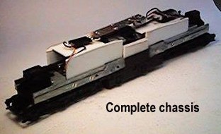
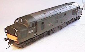
Pictures show the complete chassis and the assembled loco.
Now I have a working loco it joins the queue for cosmetic attention to the bodywork.
There is also the original Overland chassis waiting inspiration to complete the P4
conversion.
Copyright Keith Norgrove.
Last revised: August 27, 2003