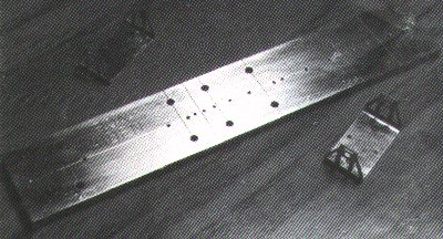
During various excursions into the field of model rolling stock in P4 over the last few years, whether scratchbuilding, kit assembly or RTR conversions, I had often wondered whether a quick and accurate method of positioning and fitting W-irons under wagon chassis could be devised. We all know that in order to produce a free-running model of correct appearance the W-irons must be fitted at correct wheelbase centres, at right-angles to the vehicle’s longitudinal centre line, and parallel to each other. Obtaining these conditions entails accurate measuring and marking and also accurate drilling, all of which takes time; in my case these operations were developing into a mental hurdle which had to be overcome before reaching the more interesting (to my mind) stages of wagon construction. One night (most of my modelling is done in the wee small hours) after setting up for a wagon session’ and reaching this stage of construction, I found myself diverted from the practical to doodling on bits of paper in an effort to come up with something that would make life easier in this department. The result is the gadget pictured and described here.
I should say at the outset that my method of fixing W-irons to wagon chassis involves the use of 12BA cheese-head bolts (2 per W-iron) with Vilene strips between the W-iron and the underside of the floor to give the necessary movement’ on one W-iron. This method was described to me many years ago by Bernard Weller and I have never seen any reason to change. Within my own circle of modelling colleagues I seem to be the only one to use this system, and on several occasions I have been questioned regarding the cost involved. "After all, l2BA bolts aren’t exactly cheap these days. old boy, and. I mean to say, four to a wagon . . . ‘ All I can say is that 400 l2BA bolts in l/8in. and 3/32in. lengths cost me £3.45 from Clerkenwell’s of London (usual disclaimer) several years ago — enough for 100 4-wheel wagons at a calculated cost of less than 3½ p per wagon and as the other exotic systems I’ve seen use brass plates, 8BA nuts and bolts, track rivets. lengths of wire or what have you, all of which have presumably to be purchased, I’m not yet convinced that I’m being extravagant. However, each to his own, and I prefer my system (or Bernard’s!) for its simplicity, ease of fitting and capability of adjustment.
The gadget itself is basically a drilling jig, with one or two other uses that can be incorporated as a bonus. It can be made from brass bar 1in. x 1/8in. or. as the one described here, aluminium bar to the same dimensions with a 1in. x 25-thou brass strip Araldited on one face to give a better surface for scribing. It is designed to be used for 4-wheel wagons of whatever wheelbase dimensions and the length of the jig is up to you, depending on how many different wheelbases you want to incorporate. For the record this particular one is 5½ in. long and will accomodate the following wheelbases: 9 ft.. l0ft.. l0ft.6in., 11ft.. 12ft.. 15ft.. 16ft.. 19ft.. 23ft.6in. and 27ft. The wheelbase dimensions you ‘build in’ can .be based on Company practice. RCH practice or simply be decided by the actual wagons you intend to construct, but should a wagon with a. differing wheelbase be subsequently encountered this dimension can always be incorporated in your jig at a later date.
An important point is to plan the arrangement of your chosen wheelbase dimensions so that things don’t become too cramped, with consequent overlapping’ of the associated guide holes. For instance. 9ft and l0ft. wheelbases are too close to be practical as the guide holes related to these dimensions get in each other’s way, but 9ft. and l0ft.6in. can be just about managed side by side. The answer is to use certain wheelbase dimensions to ‘double-up’ as zero lines for other wheelbase markings. Thus, on my jig the 9ft. line is also the base line for a l0ft, wheelbase when used in conjunction with the 19ft. line; the 12ft. line is also the datum line for a 15ft. wheelbase when used with the 27ft line, and so on. A glance at the diagram will hopefully help you to make sense of this. The wheelbase lines with large holes towards the outside edges of the jig are those which are also used as zero lines.
Marking out commences with a scribed line longitudinally along the centre of the face of the jig. Ensure that this line is equidistant from each long edge as subsequent operations are dependant upon the accuracy of this. Then a line is marked and scribed across the face 5/8in from the left-hand end, using an engineer’s try-square to ensure it is at right-angles to the centre line. This becomes your datum or zero line and all further dimensions are measured from this line. Accurate measuring and marking is the order of the day here, and all wheelbase lines should be scribed across the jig using the try-square to ensure right-angles with the centre line and the edges of the jig. When all wheelbase lines are scribed and checked for dimensional accuracy the next job is to mark and and centre-pop the fixing holes for the W-irons. I found this easiest to do by using an actual W-iron, and a useful expedient was to fix double-sided sellotape along the face of the jig to position and hold the W-iron whilst this operation was carried out. Position the W-iron on the sellotape over the zero line and line up by eye the small holes along the centre scribed line and the large holes along the zero line. Press the W-iron into the sellotape and check alignment again. When satisfied that the W-iron is correctly positioned use a scriber to mark the centres of all four holes onto the face of the jig. These centres can then be popped without removing the W-iron and the pop marks should, of course, be exactly on your scribed lines. Repeat this operation at each wheelbase line. Note that the centres of the small W-iron holes should be marked and popped at every scribed wheelbase line but the centres of the large W-iron holes should only be marked at the zero line and those wheelbase lines that are to double up as zero lines (as mentioned earlier).
When all the hole positions are marked and centre’popped remove the sellotape and clean up the face of the jig with a glass-fibre brush. The next operation is drilling and here I would advise the use of a large pillar drill or the vertical drill on a modeller’s lathe to ensure accuracy. All the pop’marks along the centre line of the jig should be drilled No. 61 (tapping size for 12BA) and the larger holes should be drilled 3/32in. to match the equivalent holes in the W-iron itself. The purpose of these larger holes in the jig will be explained later. When all drilling is completed both front and rear faces of the jig should be cleaned up and any burrs removed from the holes.
The finishing touches can be provided by marking each wheelbase line with its actual prototype dimension in relation to the zero’ line (see diagram). In order to make this as neat as possible I employed the services of the chap behind the ‘engraving/key cutting’ counter of the local branch of a large national chain store. Using a 2:1 reduction engraving machine he made a good job of engraving eight dimensions for a charge of £1.50 and was so intrigued as to the purpose of this lump of ‘holy’ metal that on receiving my explanation he insisted on spending a further 15 minutes of his lunch hour in engraving thereon its name at no extra charge! I later ran etching primer into his engraving work then repeated this operation using paint in order to make the characters stand out. This certainly improved the appearance.
I mentioned earlier that several other benefits can be found in using this jig. One of these lies in the fact that its width of lin. (25.4mm) is just the right measurement for the jig to act as a ‘spacer’ for the positioning and fitting of solebars. With the jig in position on the underside of the floor its long edges can be used to position the solebars whilst these are secured to the vehicle. Whilst doing this. use the two wheelbase lines relevant to the wagon under construction to line up the spring stops on opposing solebars. This ensures that the solebars are exactly opposite each other and that they will be correctly positioned in relation to the W-irons when fitted. The solebars will also be parallel to each other and form a correct right-angle with the floor.
After the solebars are fitted a line is scribed across the underside of the wagon floor to mark one axle position. When assembling wagon kits the position of this line can be easily determined from the above-mentioned spring stops if these are present on the solebar moulding (and they should be!). The jig is then replaced between the solebars with the desired wheelbase datum line positioned over the scribed axle line on the wagon floor. This can then be lined up by sighting through the large holes in the jig — hence the purpose of these holes. Whilst maintaining the position of the jig the four fixing holes for the W-irons can be drilled through the jig into the floor using the appropriate No. 61 guide holes in relation to the wheelbase lines corresponding to the wheelbase of the wagon under construction (phew!). Another factor to be taken advantage of here is that the depth of the holes to be drilled in the wagon floor can be controlled; by calculating how far into the floor you want to drill and adding the thickness of the jig this determines the length of drill you should have protruding from the chuck. The jig then acts as a form of depth-gauge and prevents you drilling too far into the work. Also the fact the guide holes through the jig are vertical (if you used a pillar drill) helps you to
drill accurately into the wagon floor without the holes ‘wandering’ from the vertical.
When your four fixing holes are drilled along the centre-line of the wagon underside —- that’s it. Your Vilene strips and W-irons can be positioned and the 12BA bolts screwed in. if the wagon floor is Plasticard or kit plastic the bolts will follow the holes and cut their own thread, and you know that the W-irons will be positioned at the correct wheelbase and be square to the solebars. Since using this jig I can honestly say that I have never built a wagon that didn’t run straight and true on a flat surface the instant the wheels were fitted — not always the case in earlier days I must admit. My only reservation about this jig is that repeated use of the centre-line holes as drilling guides cause these holes to wear and ‘elongate’, especially with the use of fairly soft metals such as brass and aluminium. For this reason only light pressure should be used when drilling, and as my wagon floors are usually plastic this is no great problem. I see the jig lasting for a while yet. Construction of the jig itself was a fairly quick operation. The marking out, scribing and centre-popping took just under an hour. Carefull drilling took a steady half-hour (all 24 holes). Apart from its usefulness for W-irons its beauty lies in the knowledge that all edges are straight and at right-angles to the faces, the result of using machine-cut stock material.
So much for the ‘Iron Maiden’, which has become for me one of those gadgets that you wonder how you managed without. Why the name? Well, its prime use is for fitting W-IRONS. And if there has to be a first time for everything — there’s nothing like getting it right first time!
Back to Home Page
Last revised: August 27, 2003